Phase 1. Treatment Prescription
1. Navigate to Treatment Management
Navigate to Quicklinks > Treatment Management > Prescribe Treatment
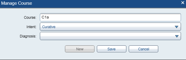
2. Create a New Course
- Click the drop down arrow and select
New

3. Enter Course Details
- Course name: C1a (first HDR treatment) or C2a (second HDR treatment)
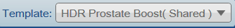
4. Select Treatment Template
HDR Prostate Boost (Shared)for boost treatmentHDR Prostate\SV (Shared)for monotherapy- This auto-populates the
Treatment Prescriptionpane (e.g., One Fraction)
Phase 2. Contouring
5. Rename CT Image
- Right-click on the
CT Imagebox (top left) >Properties - Change ID to CT HDR Prost Fx1 (adjust fraction number as needed)
6. Add HDR Prostate Treatment Structures
- Navigate to
Structure>New Structure from Template>Dunn HDR Prostate- This adds:
PTV,Prostate,Rectum,Urethra, andBladder
- This adds:
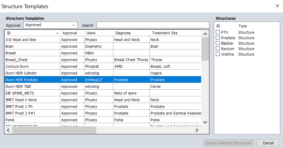
7. Contour Structures
- Quality of life: Hover over the CT display to see protocol structures. To show the structure names permanently, right click the small icon near the top left corner of the display and uncheck
Auto-hide Structure list - Efficiency: Contour every 3-4 slices, then click
Interpolate Structureon the vertical toolbar andApply - Quality Check: Scroll through all slices to verify interpolated contours and adjust as needed
We use Iodine-based contrast agents to improve visualization of the urethra and bladder. However, if the patient has a contrast allergy, imaging will be performed without contrast. In non-contrast cases:
- Sagittal views become essential for accurate urethra contouring
- Physician input and guidance is particularly important
- Fused MRI (if available) can help due to better soft tissue contrast
Rectum
CT Identification:
- Tubular structure posterior to the prostate
- May contain air (dark/black) or soft tissue density (gray)
Contouring Guidelines:
- Inferior boundary: Anorectal junction (where puborectalis sling creates posterior angulation)
- Superior boundary: Rectosigmoid junction (where bowel deviates laterally/anteriorly, typically S2-S3 level)
- Wall: Include entire rectal wall circumferentially
- Key point: Maintain clear tissue plane between rectal wall and prostate
CT Tips:
- Use
abdominalwindowing to distinguish wall from contents - Contour entire structure despite air-fluid levels
- Verify continuity on coronal and sagittal views
Some patients may have hydrogel spacers between the prostate and rectum from prior external beam treatment. These spacers can be difficult to discern on CT and may appear similar to soft tissue. If uncertain, review prior treatment records or MRI images to identify spacer boundaries.
Urethra
CT Identification:
- Runs through prostate center from base to apex
- Slightly lower density on CT; better visualized on MRI
- With contrast: appears as bright structure due to Iodine uptake
Contouring Guidelines:
- Superior boundary: At least extend up to the internal urethral sphincter (you can continue into the foley)
- Inferior boundary: Anterior tracking section, at least 2 cm away from the closest applicator
- Diameter: Typically 5-8mm
- Path: Follows natural anterior concavity through prostate
Tips:
- If Foley catheter present, contour around it
- Verify continuity on sagittal views
- Without contrast: rely heavily on sagittal/coronal views
Bladder
CT Identification:
- Large pelvic organ superior and anterior to prostate
- Fluid-filled with low CT density; thin soft tissue wall
Contouring Guidelines:
- Inferior boundary: Bladder base/neck (superior prostate aspect)
- Superior boundary: Bladder dome (extend above high-dose region)
- Include wall only, not just lumen
CT Tips:
- Filling varies—adapt to patient anatomy
- Wall typically 3-5mm when moderately filled
- Use coronal views to verify extent and wall continuity
If your digitized needles appear to pass through the bladder contour, this indicates an incorrect bladder contour—not an actual needle placement issue. Needles should never be placed through the bladder. Review and adjust your bladder contour to ensure anatomical accuracy.
Some patients treated with this protocol may not have a prostate (e.g., post-prostatectomy with local recurrence). In these cases, anatomical landmarks and contours will not follow typical appearance. Exercise additional caution and consult with the physician for guidance on target and OAR delineation.
8. Perform Image Fusion (Optional but Recommended)
Locate relevant imaging studies (MRI, PET) to assist the physician with target delineation. Image fusion can be performed before or after contouring, depending on workflow preferences.
- Navigate to
Quicklinks>Imaging>Image Registration - Check the horizontal chronological image display for available studies
- Check Epic for available imaging studies and treatment planning notes
- Review patient notes to identify which imaging study was used for disease identification
- Import that specific study if available
- Best practice: Import the most recent study of the same modality as the one used for disease identification for anatomical relevance
Create Image Registration Link
- Double-click the CT study to select it and display in all views
- Right-click on desired source image (e.g., MRI study) and select
Manual Match - In the
New Rigid Registrationwindow that appears, verify:- Source Image: Secondary imaging (e.g., MRI or previous fraction CT)
- Target Image: Planning CT with existing contours
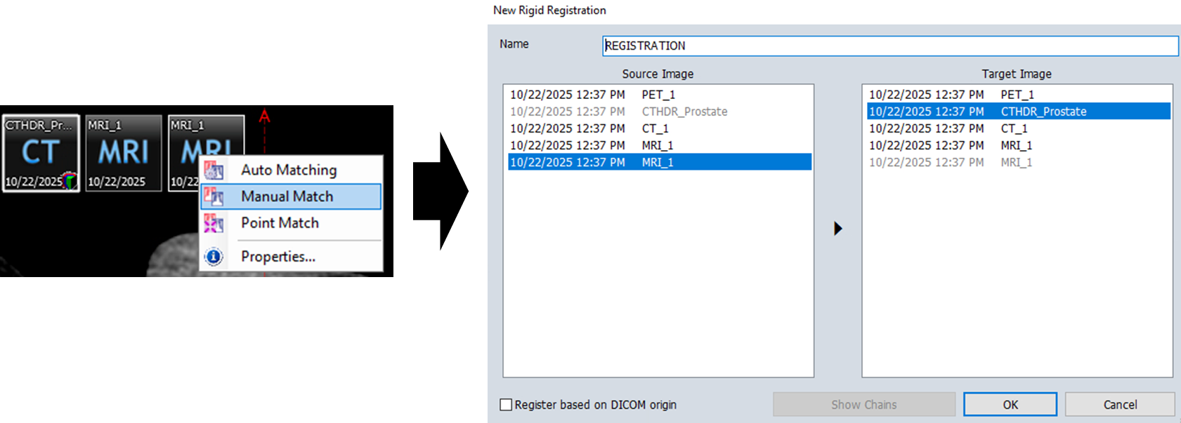
- Click
OK, you should see a line connecting yourSourceandTargetimages (A) - Obtain approximate alignment using the
Manual Matchtool
- This involves translating and rotating the images until a reasonable alignment is achieved
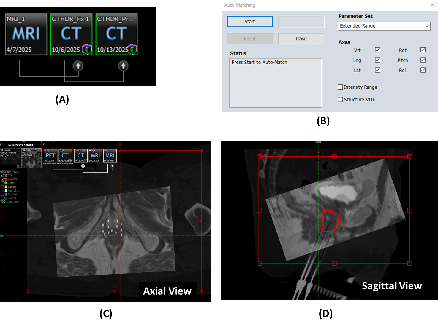
- Click
Auto Matching in the toolbar
 - Configure Auto Matching Region:
- Adjust the registration region dimensions to focus on the prostate and surrounding anatomy (C-D)
- Click
Startto begin automatic registration (B)
For second fractions, you must fuse the CT from the first fraction to the new CT to import the prostate contour. These structures (Prostate and PTV) are needed for optimization and will be reviewed by the physician.
Steps for Second Fraction Structure Import:
- First, align the current CT with the previous fraction CT using the image registration workflow described above
- Once aligned, import the prostate structure from the previous fraction
- Use the Margin for Structure tool
 to expand the imported prostate with the following values:
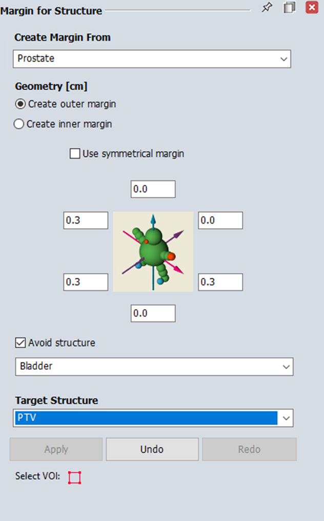
- The physician will verify and adjust these imported structures as needed before proceeding with planning
Phase 3. Planning
When creating your plan, use the following naming conventions:
- HDR_Prst_Fx1 (or Fx2) for the first (or second) fraction
- HDR_Prst_Boost for boost treatments
- The naming should reflect whether the treatment is boost or monotherapy
3.1 Creating a Plan
9. Navigate to Brachytherapy Planning
Navigate to Quicklinks > Treatment Planning > Brachytherapy Planning
10. Open the relevant course and imaging set
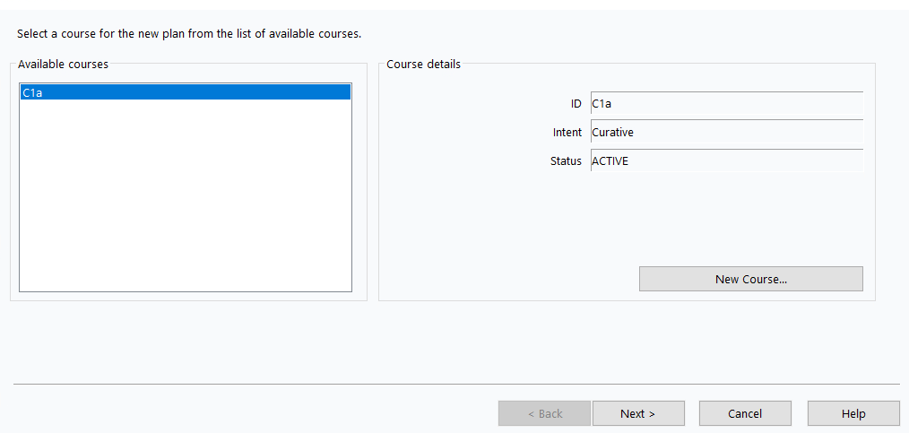
11. Create new plan
Insert>New Plan> Select your Brachytherapy Course (e.g., C1a) >Next >
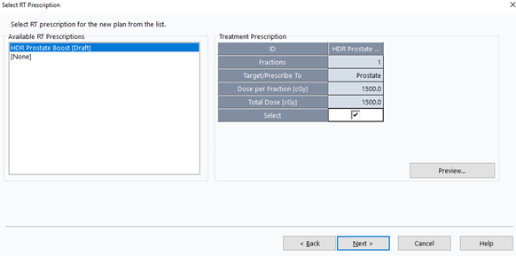
12. Select RT Prescription
- Select the prescription from Phase 1 >
Next >
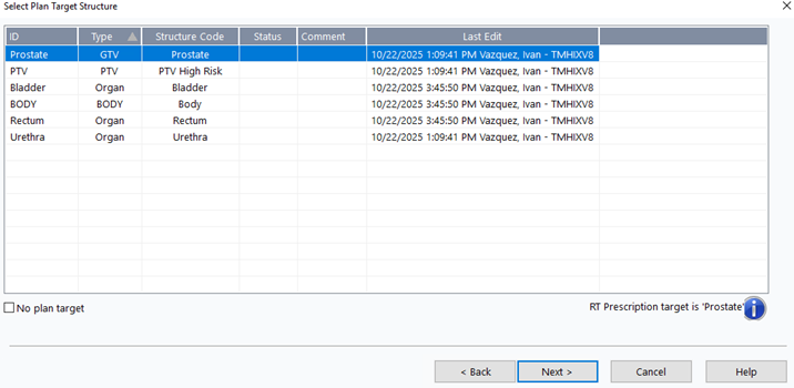
13. Select Plan Target
- Choose
Prostate>Next >
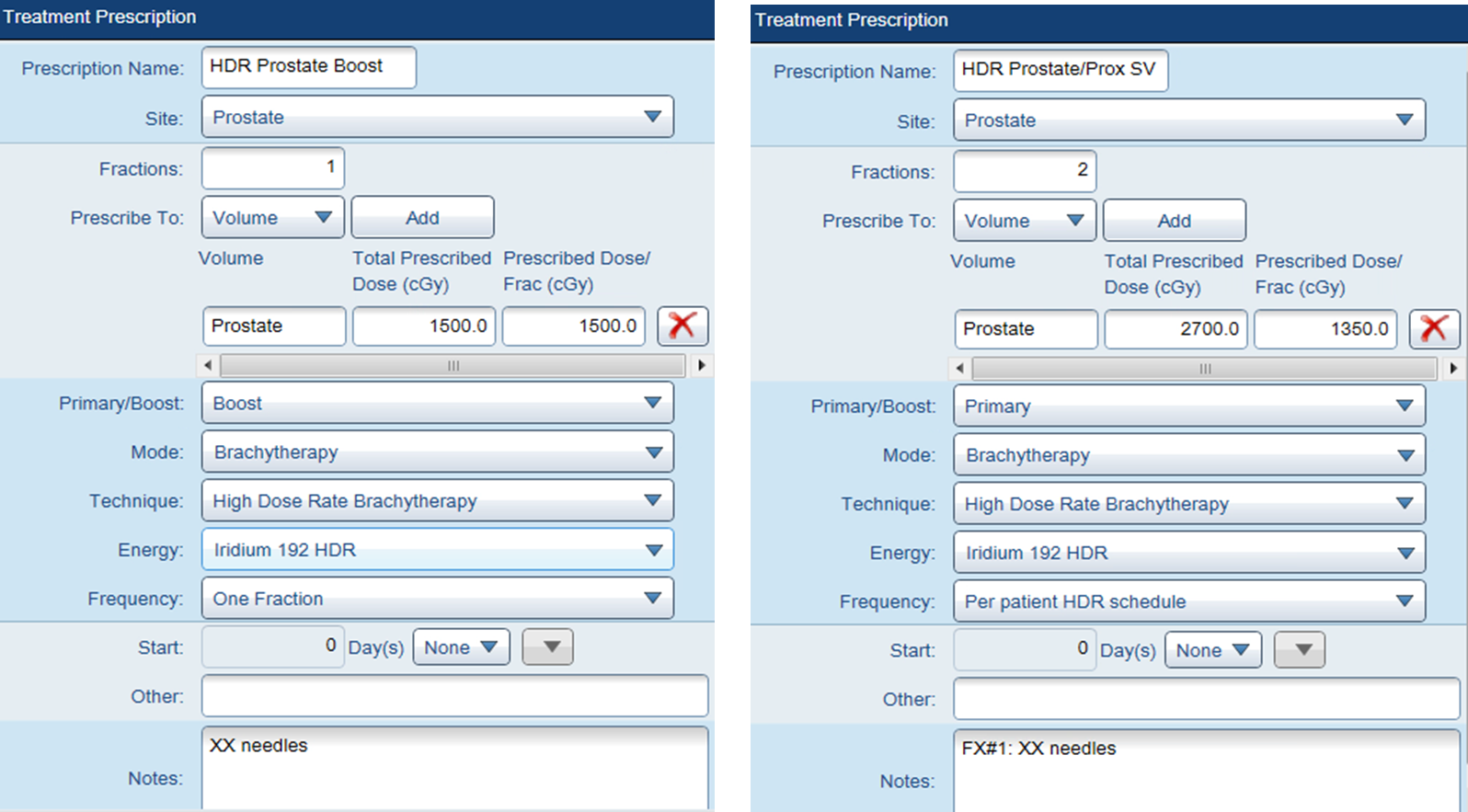
14. Configure Plan Properties
- ID:
HDR_Prost_FX1(adjust fraction number as needed) - Target Volume:
Prostate - Technique:
INTERSTITIAL - Number of Fractions:
1 - Treatment Percentage:
100% - Dose per Fraction:
1350cGy (boost) or1500cGy (monotherapy)
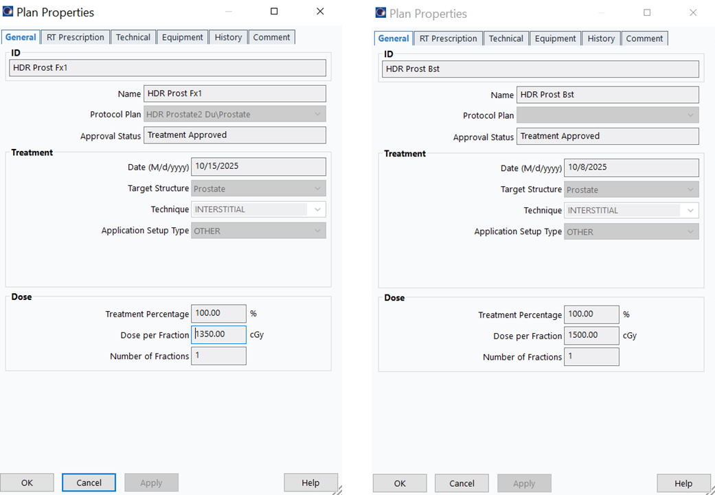
Prostate plans are always 1 fraction since we create a new plan for each fraction. In HDR Cylinder, the plan uses 5 (or 3) fractions, changed to 1 when sending to Mobius.
3.2 Insert Applicators
15. Create First Applicator
Insert>New Applicator...> SelectTreatment Unit(e.g.,Bravos - Dunn) >OK
Ensure you select the correct afterloader (Treatment Unit) for the clinic where the treatment will be delivered. Using the wrong afterloader can cause delivery errors and treatment delays.
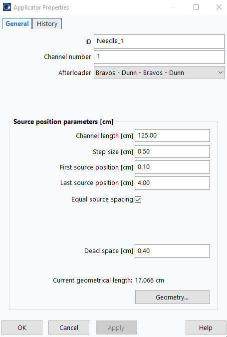
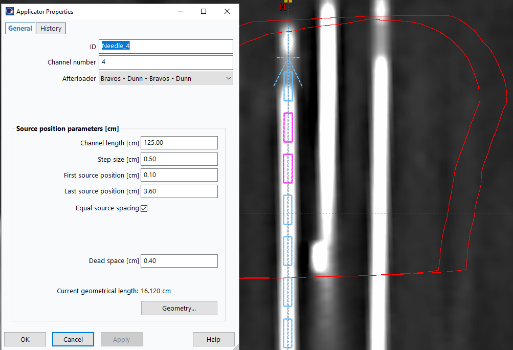
16. Configure Applicator Properties
Double-click applicator icon in data tree:
- ID:
Needle_1 - Channel length (cm):
125 - Step size (cm):
0.50 - First source position (cm):
0.1 - Last source position (cm):
4.00(adjust later as needed) - Dead space (cm):
0.4
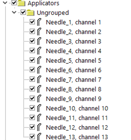
17. Duplicate for Additional Channels
- Copy and paste applicator once per expected channel
3.3 Digitize Applicators
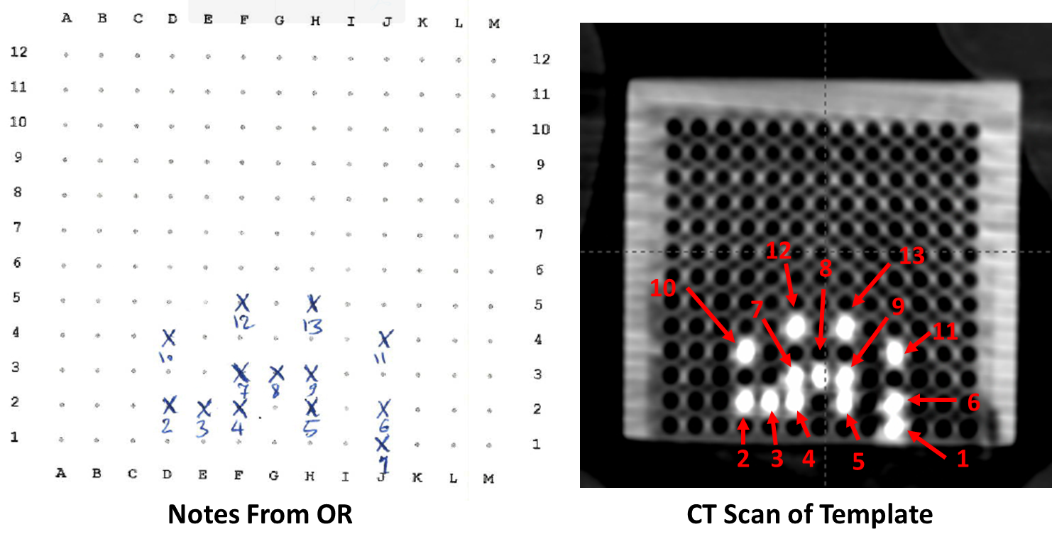
For template-based implants, use the assisted digitization method (3.3.1). For freehand implants without a template, manual digitization (3.3.2) may be more appropriate.
During digitization, select channel numbers based on your template sheet, which records the grid locations and assigned labels for each applicator/needle.
18. Align CT to Template
- Rotate axial plane parallel to template's flat face
- This ensures high-intensity points match the template pattern
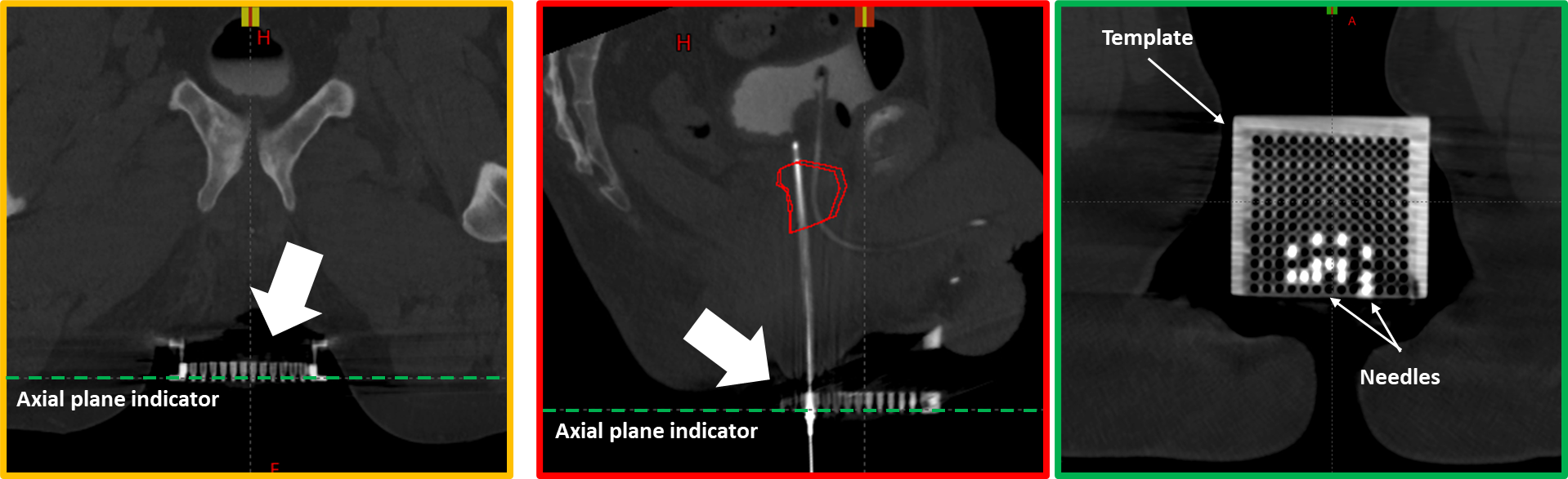
19. Orient for Template Comparison
- Adjust the viewing orientation so that the needle arrangement on screen closely resembles the template sheet from the OR
- The goal is to make channel identification straightforward by matching the visual pattern
- This allows easy verification that each digitized needle corresponds to the correct template position and label
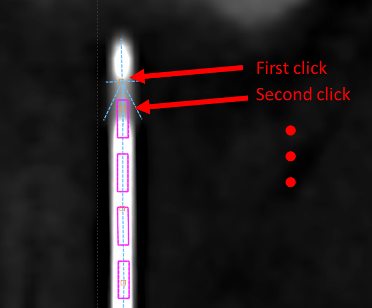
3.3.1 Assisted Digitization (Template Cases)
20. Select Appropriate Axial Slice
- Navigate just beyond the template where needle arrangement still matches template sheet
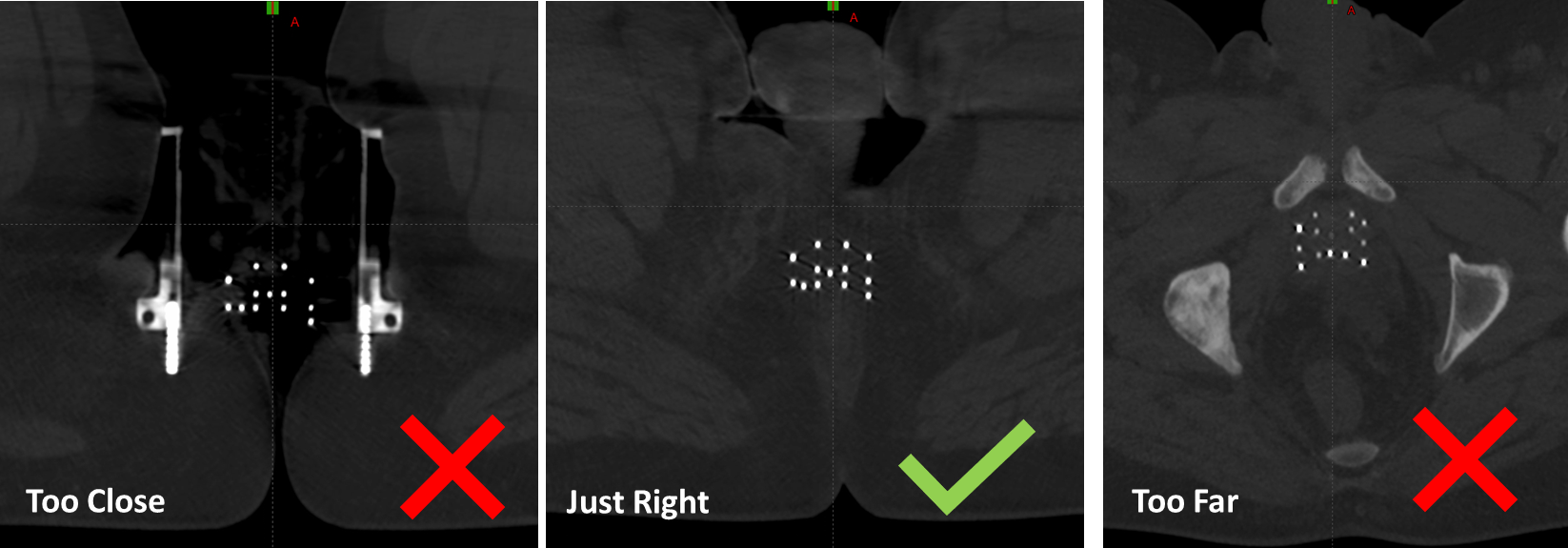
Avoid navigating too far from the template—bending can distort positions. Select a slice beyond the template for better detection while maintaining easy channel identification.
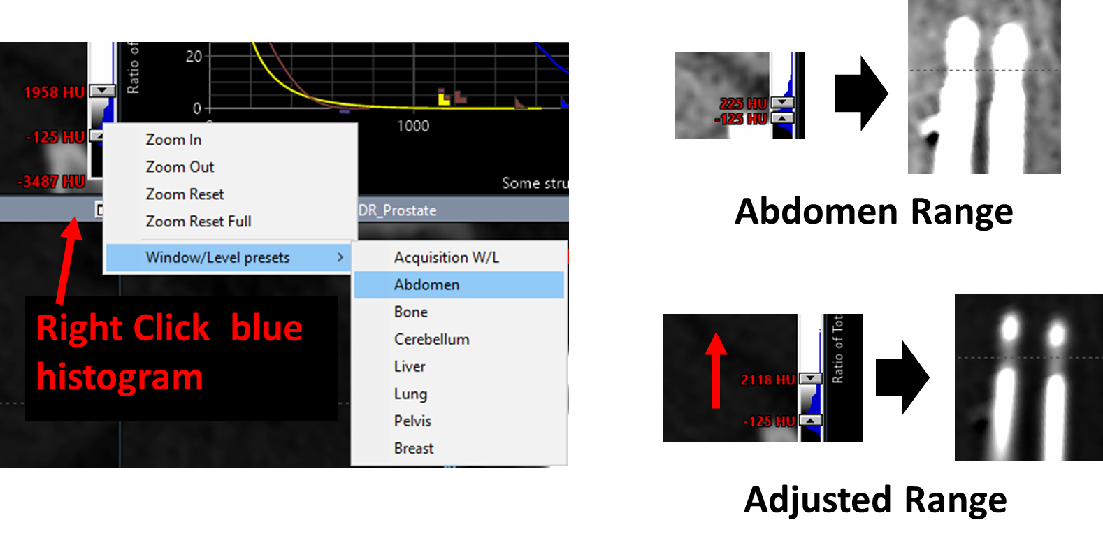
21. Optimize CT Display for Needle Visualization
- Set window/level to
Abdomenrange - Increase upper HU limit to better visualize metal needles and dead space (bright tips)
22. Detect First Applicator
- Select first channel in data tree (
Applicatorsfolder)
- Click
Detect applicator from volume image
- Click on needle location in image
- Configure settings:
MetalandStraightfor Ti needles - Adjust Threshold until applicator region appears green in Detection Threshold window
- Click
Detect Selected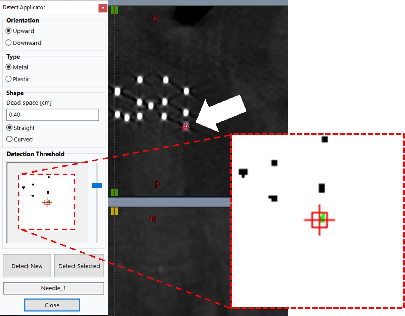
23. Detect Remaining Applicators
- With
Detect Applicatorwindow still open, select next applicator (e.g., Needle_2) - Click corresponding needle on axial slice—should turn green if threshold is correct
- Click
Detect Selected - Repeat for all remaining applicators following steps (1) - (4) below, where (1) involves checking your template sheet
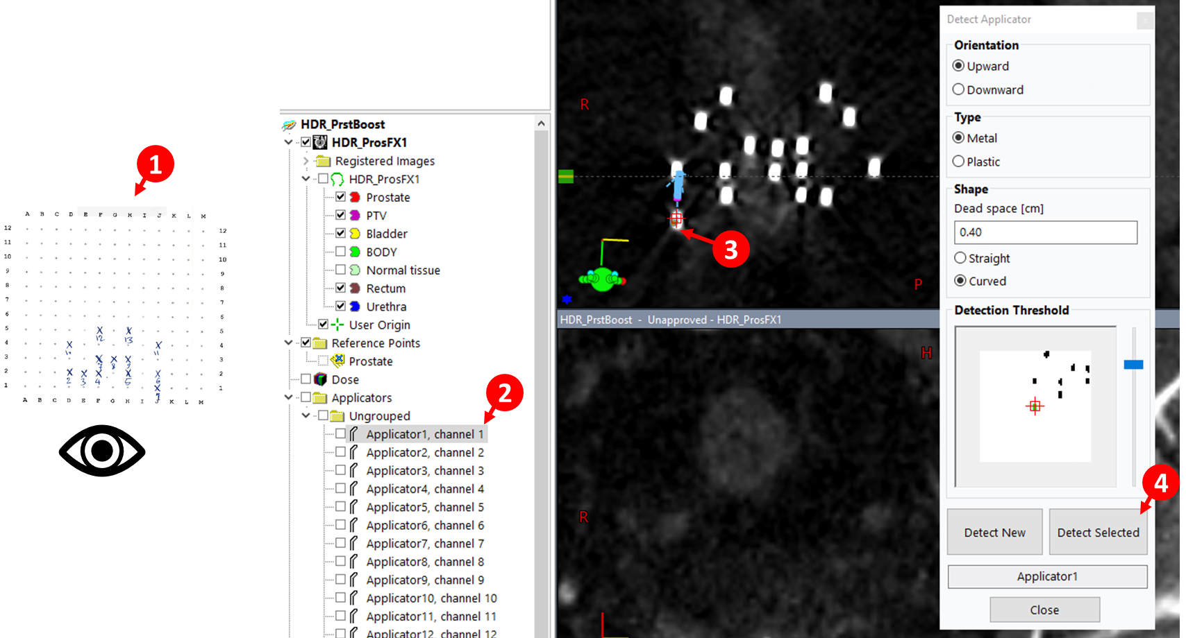
Detected digitizations are not active until modified using the edit, rotate, or translate tools 
3.3.1.1 Adjust Tips and Source Positions
24. Adjust Needle Tips
- Right-click applicator name in data tree >
Move Viewing Planes to Tip - With
Contour Editor tool selected, adjust the last point (tip)
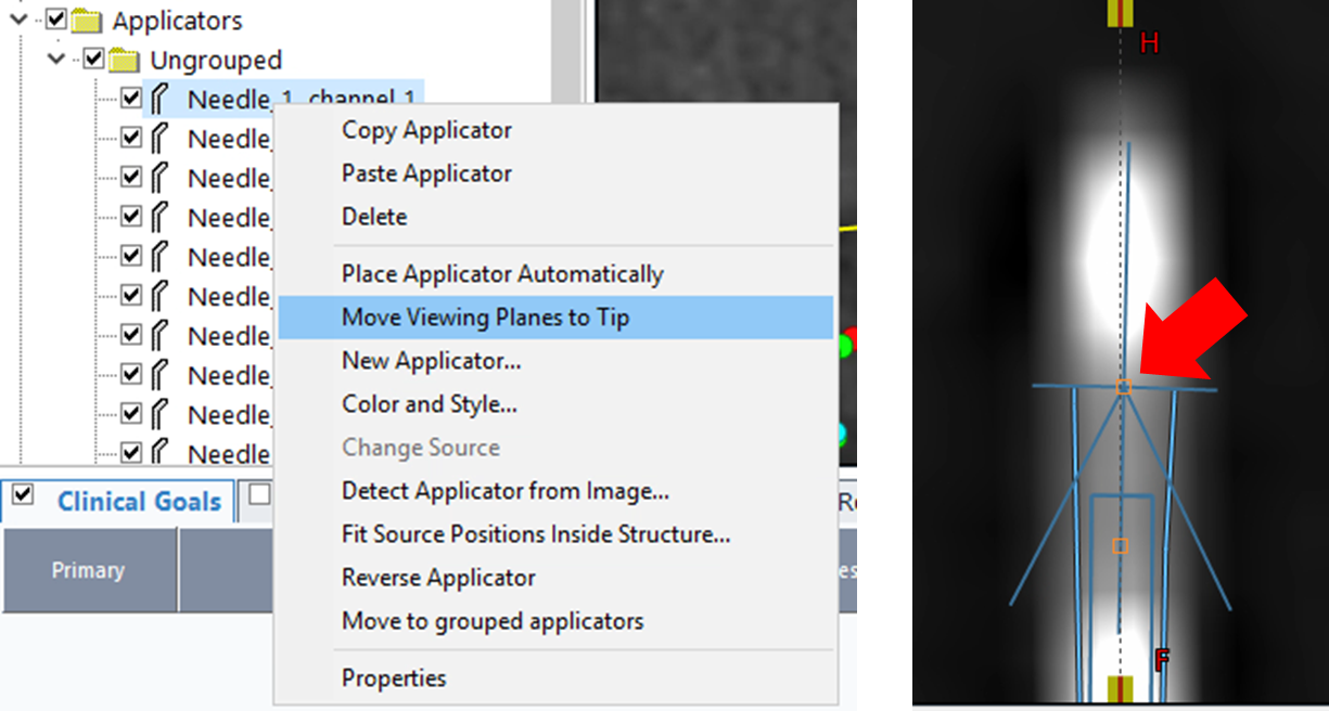
You cannot undo in this module. If you accidentally add a new point (added from the end, not tip), left-click to remove it. For more serious distortions to the applicator, it may be easier to re-digitize the applicator.
25. Update Last Source Position
The prostate contour must be drawn by the physician before you can accurately adjust the last source position to match target margins. Coordinate with the physician to ensure the prostate structure is finalized before proceeding with source position optimization.
- For each needle, adjust
Last source positionproperty to prevent dwell positions from extending beyond target margins - Extend value if initial 4 cm is insufficient
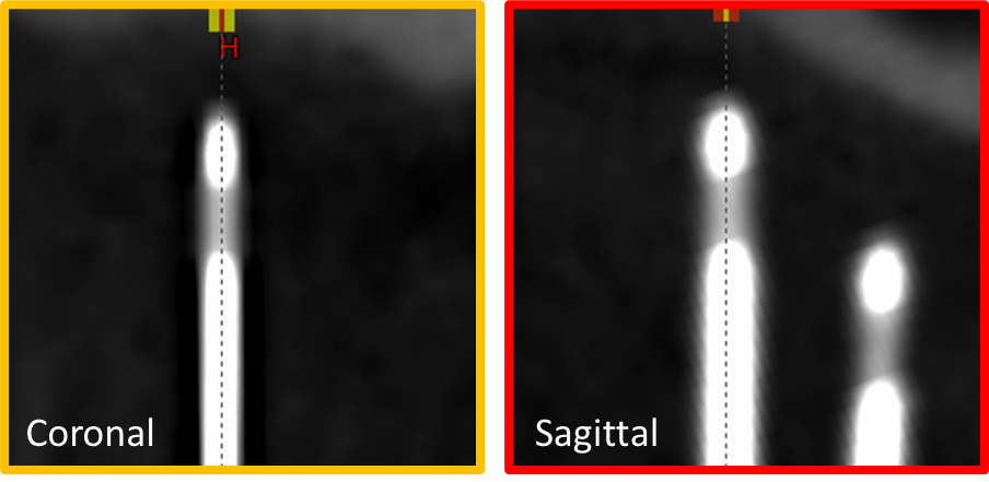
26. Inspect and Refine
- Review digitization using
Draw applicator-plane intersections with given diameter
- Verify the following quality checks:
- Continuity: Each applicator appears as a continuous line without breaks or jumps
- Template accuracy: Needle positions match the expected template grid locations
- Tip position: Tips are positioned appropriately relative to target anatomy
- Dwell position count: Number of source positions is appropriate for target size
3.3.2 Manual Digitization
27. Optimize CT Display
- Refer to step 21 above for CT window/level optimization to visualize needles
28. Align Viewing Planes
- Rotate viewing planes so needle's central axis is approximately coplanar with sagittal and coronal planes
29. Digitize Using Contour Editor
- Select Contour Editor tool

- On sagittal or coronal plane, click along applicator length to add points
- Continue until all potential dwell positions are included
- Click and drag orange squares to adjust digitization
- Right-click orange square to remove a point
30. Adjust Tips and Source Positions
- Follow steps 24-26 above to refine tip positions and update last source position values
3.4 Dose Optimization
3.4.1 Add Clinical Goals
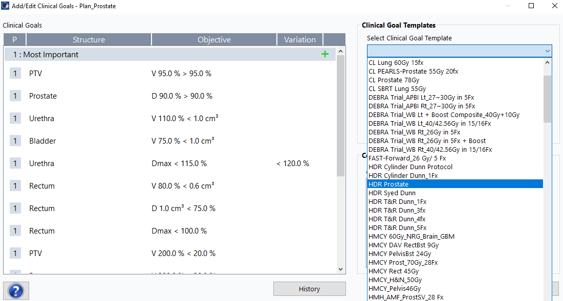
31. Navigate to Clinical Goals
Planning>Add or Edit Clinical Goals...- From
Select Clinical Goal Templatedropdown, selectHDR Prostate - Click
Ok
3.4.2 TG-43 Volume Optimization
Clinical goals must be assigned to the plan before performing VEGO TG-43 optimization. If you encounter an error during optimization, verify that clinical goals have been added by navigating to Planning > Add or Edit Clinical Goals... and following the steps in section 3.4.1 above.
32. Initiate Optimization
Planning>Modify Dose>VEGO TG-43 Volume Optimization- Click
OKwhen prompted about normal tissue structure creation
Ensure that the "Start with current dwell times" checkbox remains unchecked unless you are refining an existing optimization. Starting with a fresh optimization typically produces better results for initial planning.
33. Configure Optimization Parameters
- Click
Add from clinical goalsbutton (1)
(1) - Set
Max (s)dwell time to 5-15 seconds (2) - Slide
Smoothbar to MAX (3) to regulate dose distribution smoothness - Set the
Max basal doseto 115% of the prescription dose to control maximum dose within the target (4) - Click
Optimize, thenOK - Inspect resulting dwell times (5) to ensure the distribution is reasonable (e.g., no large spikes showing long dwell times concentrated in a few positions)
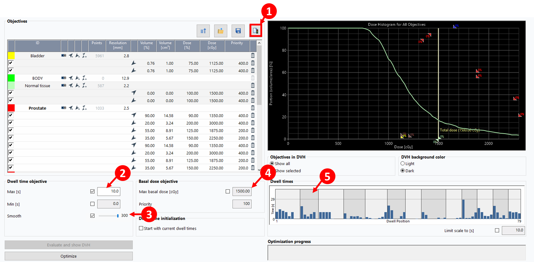
34. Add Upper and Lower Objectives (Optional)
Adding upper and lower objectives can provide additional control over the dose distribution. This step is optional but may improve plan quality in certain cases.
- Click the objectives icon
 in the optimization window
 - A dialog box will appear asking for the desired dose for normal tissue, pre-populated with the prescription dose
- Click
OKto accept the default value - In the objectives list, modify both upper and lower constraints:
- Set Volume [%] to
0 - Set Dose [%] to
100 - Set Priority to
400
- Set Volume [%] to
- The optimization constraints shown in the image above reflect these settings
3.4.3 Configure Isodose Levels
35. Set Standard Isodose Levels
Before dose shaping, configure the four standard isodose levels:
- Navigate to isodose level settings (typically in the display or dose visualization menu)
- Ensure exactly four levels are displayed: 200%, 115%, 100%, 50%
- Verify line thicknesses: All isodose lines should have consistent thickness for clear visualization
- Set color scheme and thickness:
- 200%: Yellow, 2
- 115%: Cyan, 2
- 100%: Red, 3
- 50%: Deep Blue, 2
- These settings should be configured before proceeding to dose shaping
3.4.4 Dose Shaper Refinement
36. Adjust Dose Distribution with Dose Shaper
- After initial optimization, use
Dose Shapertool to fine-tune dose distribution
 - Access via the icon
 on the tool bar or
 Planning>Modify Dose>Dose Shaper
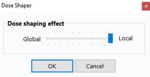
For more localized control, right-click on a view (e.g., axial view) and slide the Dose shaping effect slider all the way to Local. This gives you finer control over dose sculpting in specific regions.
- While holding
Ctrl, click and drag isodose lines to manually sculpt dose around target - Focus on:
- Reducing hot spots in urethra and rectum
- Ensuring adequate target coverage
- Minimizing dose to bladder
- Changes update dwell times in real-time
- Click
Calculate 3D Dose to see the impact of the dose on the Clinical Goals
Dose Shaper is particularly useful for addressing localized hot spots that automated optimization may not fully resolve, especially near critical structures like the urethra.
If you need to change the dose per fraction value after optimization (e.g., you initially used the boost dose but meant to use monotherapy dose), BrachyVision will prompt you with a warning and automatically rescale the dwell times accordingly. This means you can correct the dose per fraction without re-optimizing from scratch—the system will proportionally adjust all dwell times to meet the new prescription.
Phase 4. Post-Planning Review and Approval
The physician will modify and finalize the dose distribution. The physician's final dose is what we use to proceed. We make changes as described below with the aim to not induce significant changes to the dose modified by the physician.
4.1 Review and Adjust Dwell Times
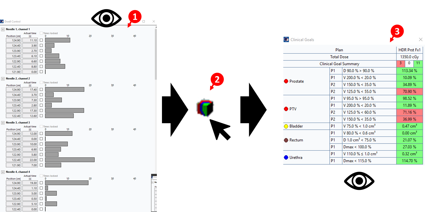
37. Inspect Dwell Time Distribution
- Navigate to
Window>Dwell Control Window - Inspect dwell times for each position in each applicator/needle to ensure values are acceptable (1)
38. Adjust Short Dwell Times
- Review all dwell time values to ensure they are above 0.5 seconds
- Make the following adjustments:
- Set dwell times ≤0.3 seconds to
0(remove) - Set dwell times of 0.4 seconds to
0.5(minimum acceptable)
- Set dwell times ≤0.3 seconds to
- These modifications ensure reliable source positioning and delivery
39. Recalculate Dose
- After making dwell time adjustments, click
Calculate 3D Dosebutton (2) - Verify that clinical goals are still met
- Ensure changes did not significantly alter the dose distribution
- If clinical goals are no longer satisfied, make minor adjustments and recalculate
The main objective is to ensure that clinical goals remain met and do not change significantly after small modifications to dwell times. Once acceptable, proceed to Mobius verification.
4.2 Mobius Secondary Calculation
40. Create Mobius Reference Point
- Move the axial plane to a central region of the target volume
- Right-click
Reference Pointsin the left panel - Select
New Reference Point And Location - Click anywhere on the images in the right panel to place the point initially
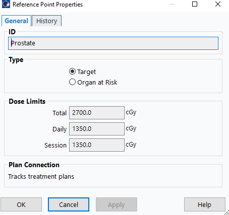
41. Configure Reference Point Properties
- In the properties dialog:
- Name:
Mobius Fx1(assuming first fraction) - Type:
Target
- Name:
- Click
OK
42. Position the Calculation Point
- Position the point on the 100% isodose surface
- Place the point away from needle positions to ensure accurate dose calculation
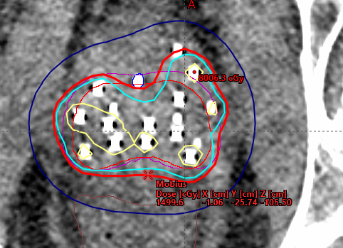
This reference point is used for independent dose calculation verification in Mobius. It should be positioned in a representative location within the target volume where dose can be reliably calculated and compared.
43. Export Plan to Mobius
- Right-click plan name >
Export>Mobius3D - Server 3 - Click blue arrow >
Authorize - Verify all files transferred successfully
Ensure number of fractions is set to 1 before export.
44. Access Mobius Report
- In your browser, navigate to Mobius Server by typing the IP as your URL (e.g.,
10.110.16.21) - Log in with credentials
- Click patient name >
Open PDF Report
45. Verify Agreement
- Scroll to bottom of plan data
- Confirm percent difference shows green checkmark (Mobius 2nd Check & Eclipse agree within tolerance)
- Save report to P-drive as
4-mobius- Navigate to
P:\1. Methodist Dunn\3B. HDR Bravos Dunn\1. HDR Patient QA - Create a folder using the patient's name if it doesn't exist
- Save the PDF in the patient's QA folder
- Navigate to
Each patient should have a QA folder where you place files for each fraction, including:
- Scanned template form from OR
- Mobius calculation report
- Other QA documentation as needed
46. Clean Up Eclipse Plan
- Return to Eclipse plan
- Delete
Mobius Fx1reference point before proceeding with plan approval
Mobius point only needed for calculation documentation; removing improves screenshot clarity for final documents.
4.3 Plan Approval and Documentation
47. Approve HDR Plan
- Right-click plan >
Plan Approval>Planning Approved - Acknowledge minor warnings (unapproved/rejected structures)
- Enter credentials for verification
The plan must be in Planning Approved status before generating treatment documents. During approval, you will need to specify the dose limits for the prostate reference point (target). Ensure these values are correctly entered as shown below:
48. Create Plan Report
File>Print>Report- Printer:
Adobe PDForMicrosoft Print to PDF - Layout:
BrachyFull.tml - Ensure the
LayoutinPropertiesis set toPortrait> ClickOK - Save to patient path as 1-report
49. Create Orthogonal Views Screenshot (With Clinical Goals)
- Double-click
User Origin - Display
Clinical Goalstab in bottom panel File>Print>ScreenProperties>Layout: Change toLandscape- Click
OK - Save to patient path as 2-iso-with-goals
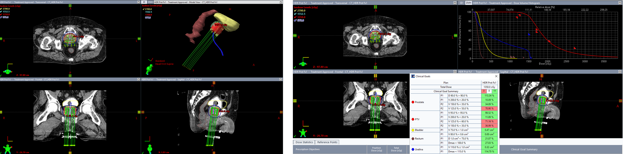
50. Create Orthogonal Views Screenshot (Without Clinical Goals)
- Hide
Clinical Goalspanel - Right-click top-right window > Select
Show 3D View - Adjust 3D view to show a clear perspective of the needle arrangement
File>Print>ScreenProperties>Layout: Change toLandscape- Click
OK - Save to patient path as 2-iso-3d-view
The screenshot without clinical goals should showcase the 3D needle arrangement for physician review and documentation purposes. Ensure the view clearly displays the spatial relationship of needles relative to the target and critical structures.
51. Create DVH Report
Dose Statisticstab: Check all structures for DVH display- Click DVH panel
 (Above top-right or "3D" window)
 - Right-click >
Print DVH Report - Ensure the
LayoutinPropertiesis set toLandscape> ClickOK
Ensure the DVH x-axis displays absolute dose (Gy) rather than percentage. This provides clearer clinical interpretation of the dose distribution.
- Save to patient path as 3-dvh
52. Combine Documents
- Select all files (1-report, 2-iso-with-goals, 2-iso-3d-view, 3-dvh, 4-mobius)
- Right-click >
Combine files in Acrobat - Save combined PDF in patient folder
53. Upload Combined Plan Document
- In Aria, use the Import button
 (not the New button
  )
) - Select the combined PDF created in step 52
- Set the template name to:
HDR Prostate Fx1(or Fx2) for monotherapy fractionsHDR Prostate Boostfor boost treatments
The Import button is used for uploading existing documents (like your combined PDF), while the New button creates new documents from templates. Always use Import for the combined plan document.
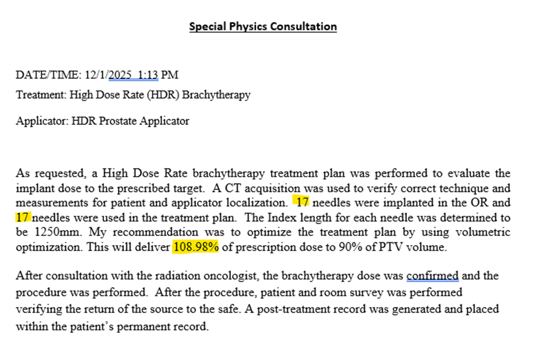
54. Create Special Physics Consultation
- Click the New button
- Select template:
HDR Prostate Consult - Complete the required fields:
- Number of needles implanted: Total needles placed during the procedure
- Number of needles used: Needles included in the final treatment plan
- D90 value: The dose covering 90% of the target volume (from clinical goals)
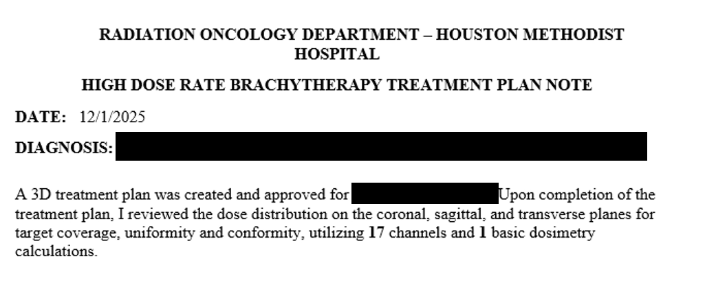
55. Create Tx Plan HDR Note
- Click the New button
- Select template:
Tx Plan HDR Note - Complete the required fields:
- Number of channels (needles): Enter the number of needles used in the plan
- Number of dosimetry calculations: Enter
1(corresponds to the single Mobius secondary calculation)