1. Preliminary Steps
1.1 Create Treatment Prescription
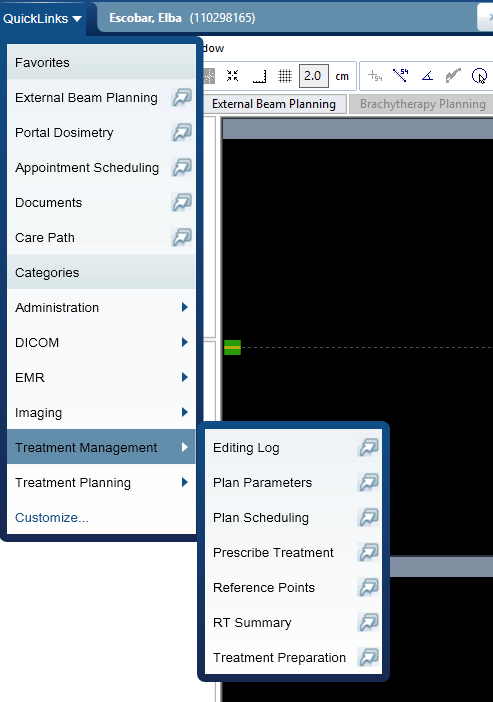
1. Open Prescription Interface
Quicklinks>Prescribe treatment
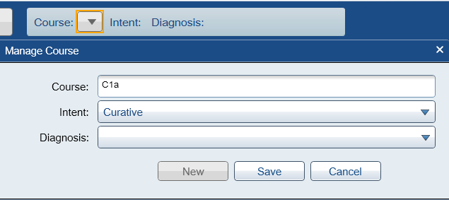
2. Create New Course
- Create new treatment course if one doesn't exist
- Naming convention: Use suffix
a(indicates brachytherapy) - Example:
C1a
3. Select Template
- Template:
HDR Cylinder (Shared) - Verify auto-populated fields match patient requirements

4. Verify Prescription Parameters
The template auto-populates the fields. Confirm the following values match patient requirements:
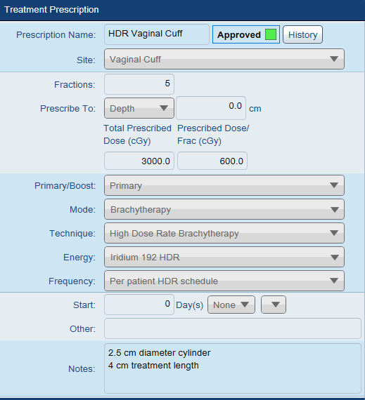
- Fractions:
3(with EBRT boost) or5(monotherapy) - Total Prescribed Dose:
3000.0 cGy - Dose per Fraction:
600.0 cGy - Primary/Boost: Select appropriate option
- Notes: Record cylinder diameter (e.g., "2.5 cm diameter cylinder, 4 cm treatment length")
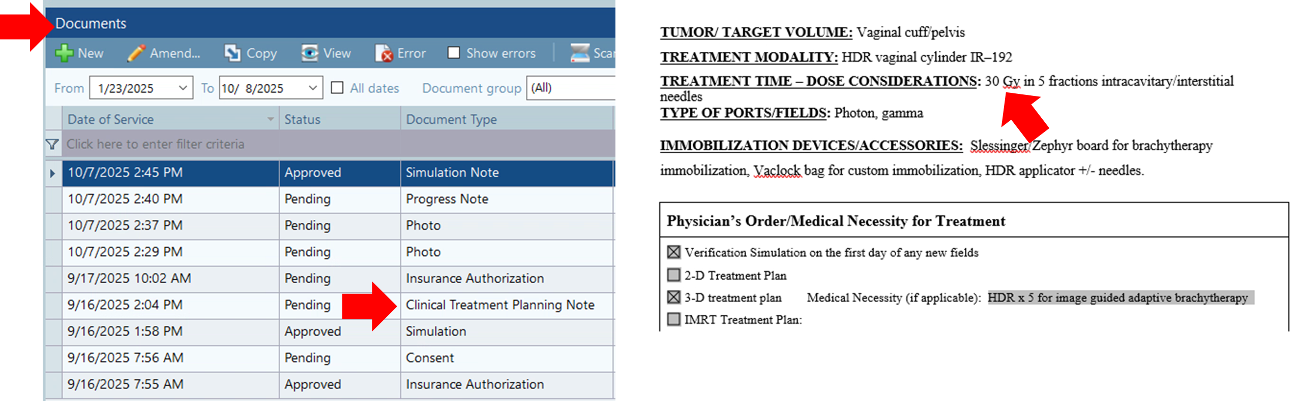
Check the Clinical Treatment Planning Note to confirm total prescription matches plan.
5. Save Draft
- Click
SAVE AS DRAFT
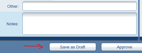
Saving as draft prevents premature physician approval before physics review is complete.
2. Contouring
2.1 Confirm Cylinder Dimensions
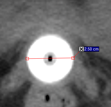
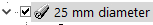
6. Measure Cylinder Diameter
- Open patient in contouring application
- Click
Distancetool to measure
 - Measure cylinder diameter
- Round to nearest standard size (2.5 cm or 3.0 cm)
7. Update CT Study Name
- Right-click CT study icon >
Properties - ID field: Rename to
HDR_CYL_XXmm(where XX = diameter in mm) - Alternative naming:
HDR CYL X.X cm(some physicists prefer cm)
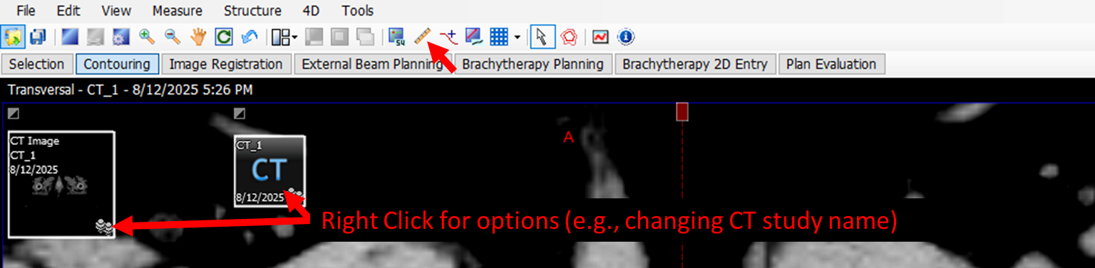
This CT name will be used for the plan name in subsequent steps.
2.2 Load Contour Template
8. Add Structure Set
- Option A:
Structuremenu >New Structures From Clinical Protocol>HDR CYL Dunn>Attach...>OK - Option B: Right-click CT >
New Structures From Clinical Protocol
2.3 Contouring Guidelines
General Principles:
- Contour ≥2 cm superior to cylinder tip (dose becomes negligible beyond this point)
- Skip 2–3 slices between contours, then use
Interpolate Structure - Verify interpolated contours on all slices before proceeding
- Use abdominal windowing to distinguish bowel wall from contents
- Check coronal and sagittal views to ensure anatomical continuity
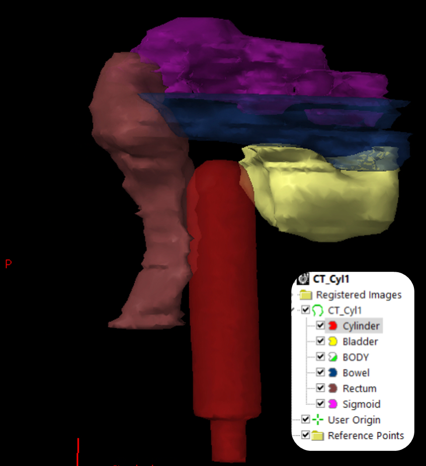
2.3.1 Cylinder
9. Contour Cylinder
- Method 1 (Adaptive brush): Set radius large enough to capture full cross-section with single click
- Method 2 (Fixed brush): Use circular brush matching cylinder diameter; adjust near dome and tip
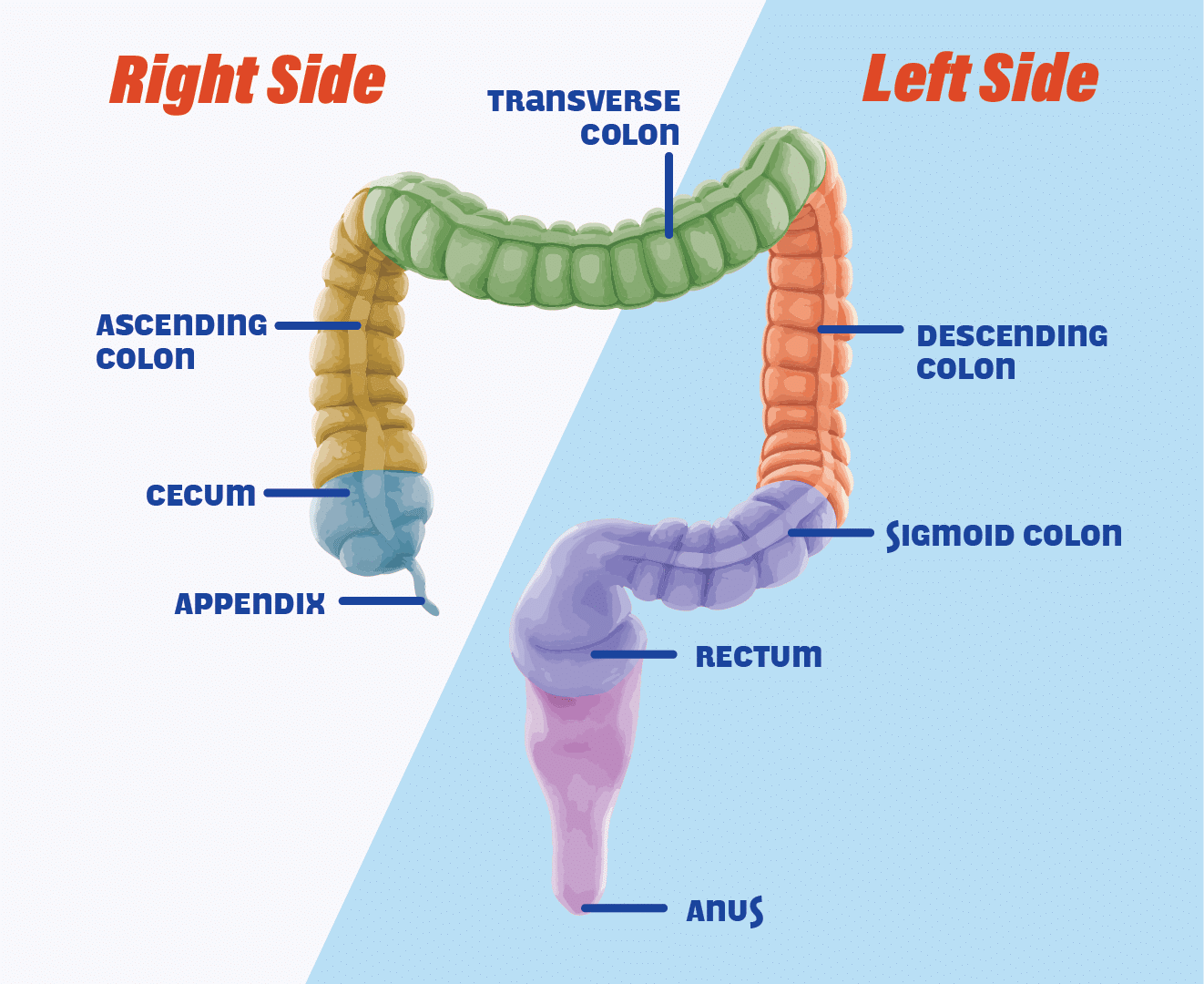
2.3.2 Rectum
10. Contour Rectum
- Inferior boundary: Start ≥2 cm below active treatment length
- Superior boundary: Extend to rectosigmoid junction (where bowel deviates laterally/anteriorly, ~S2–S3 level)
- Critical: Maintain clear tissue plane between rectum and cylinder (should not touch)
Rectum appears as tubular structure posterior to cylinder; may contain air (dark) or soft tissue density (gray).
2.3.3 Sigmoid Colon
11. Contour Sigmoid
- Starting point: Rectosigmoid junction (where rectum curves anteriorly/laterally)
- Superior extent: Continue 2–3 cm above cylinder tip
- Include all visible segments even if appearing discontinuous on axial slices
- Verify continuity using coronal/sagittal views
2.3.4 Bowel Bag
12. Contour Bowel Bag
- Definition: Small bowel and remaining bowel loops not contoured as rectum/sigmoid
- Superior boundary: 2 cm above cylinder tip
- Inferior boundary: Top edge of cylinder
- Exclude: Muscle, bone, bladder, uterus, major vessels, rectum, sigmoid
3. Plan Creation
3.1 Load Patient Data
13. Open Course and Structure Set
- Open Objects
- Highlight Patient > Select relevant course >
Apply - If not already done, name the course
C1a - Expand
All Structure Sets> HighlightCT_1>Apply
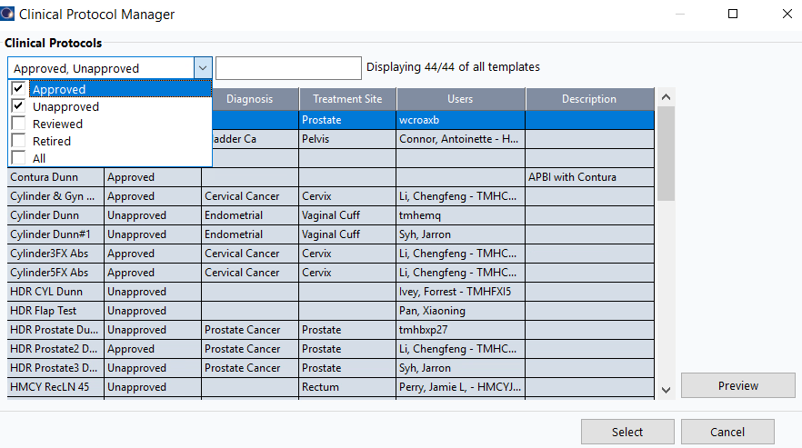
3.2 Add Clinical Protocol
14. Insert Protocol Reference
- Select course (e.g.,
C1a) >Insert>New Clinical Protocol Reference - Click
Next> SelectHDR CYL Dunn>Select
Check box for unapproved protocols to see HDR CYL Dunn.
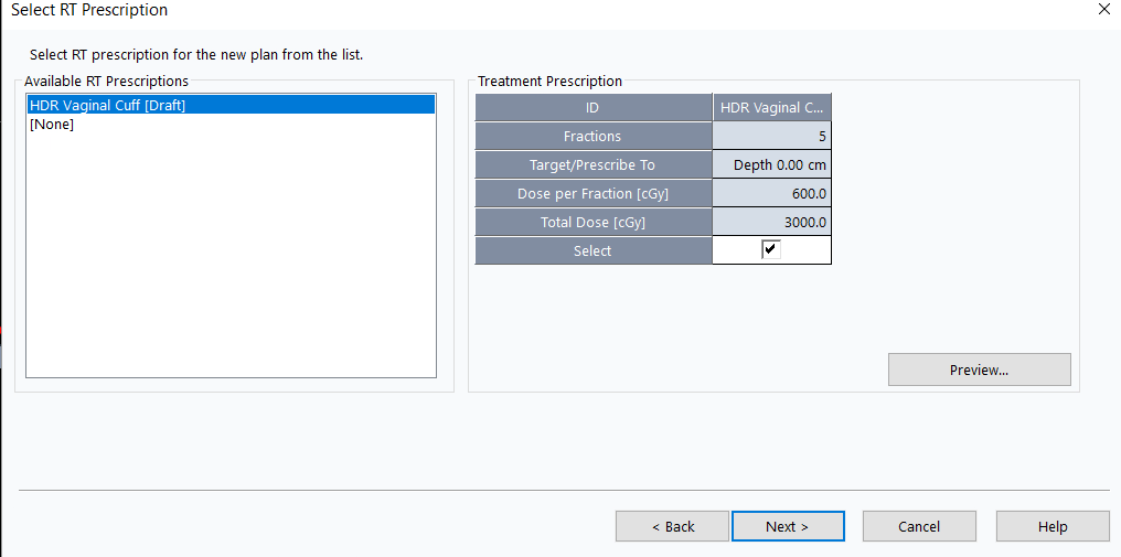
3.3 Create Plan from Template
15. Insert New Plan
- Select course >
Insert>New Plan from Template - Select prescription (e.g.,
HDR Vaginal Cuff) >Next
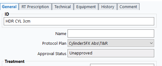
16. Select Plan Template
- Enable viewing of approved and unapproved templates
- Search for
HDR CYL Xcm(where X = cylinder diameter) - Select matching template
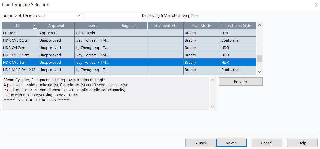
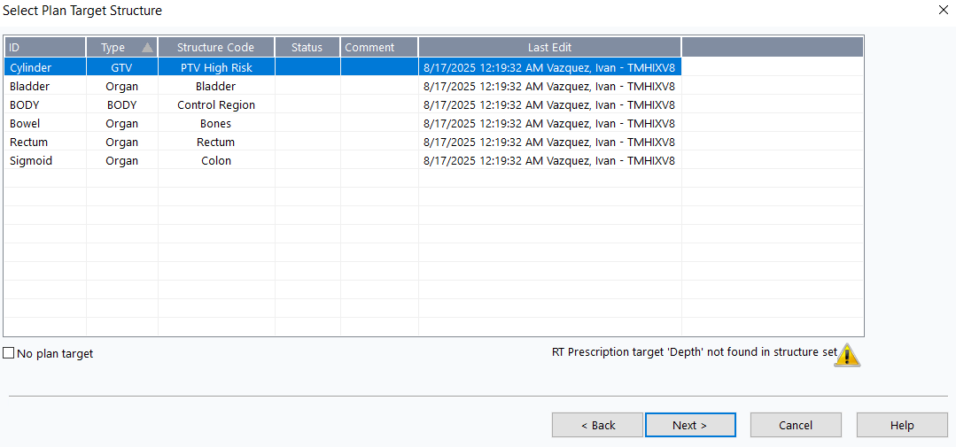
17. Configure Plan Settings
- Target structure:
Cylinder>Next
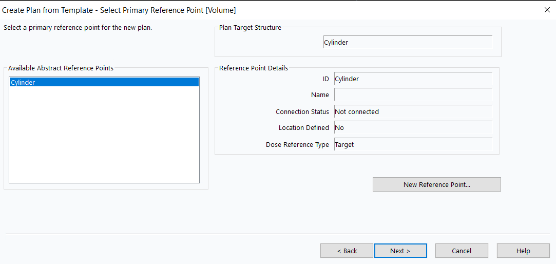
- Primary reference point:
Cylinder>Next
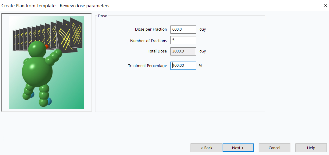
- Verify dose per fraction and total dose match prescription >
Next
If plan is not associated with clinical protocol, double-click plan name > Select relevant Protocol Plan.
3.4 Position Applicator
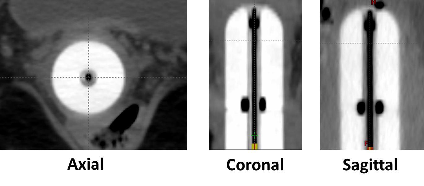
18. Orient CT Views
- Use
Rotatetool to align cylinder vertically
 - Align sagittal and coronal planes so orthogonal plane markers run along cylinder middle
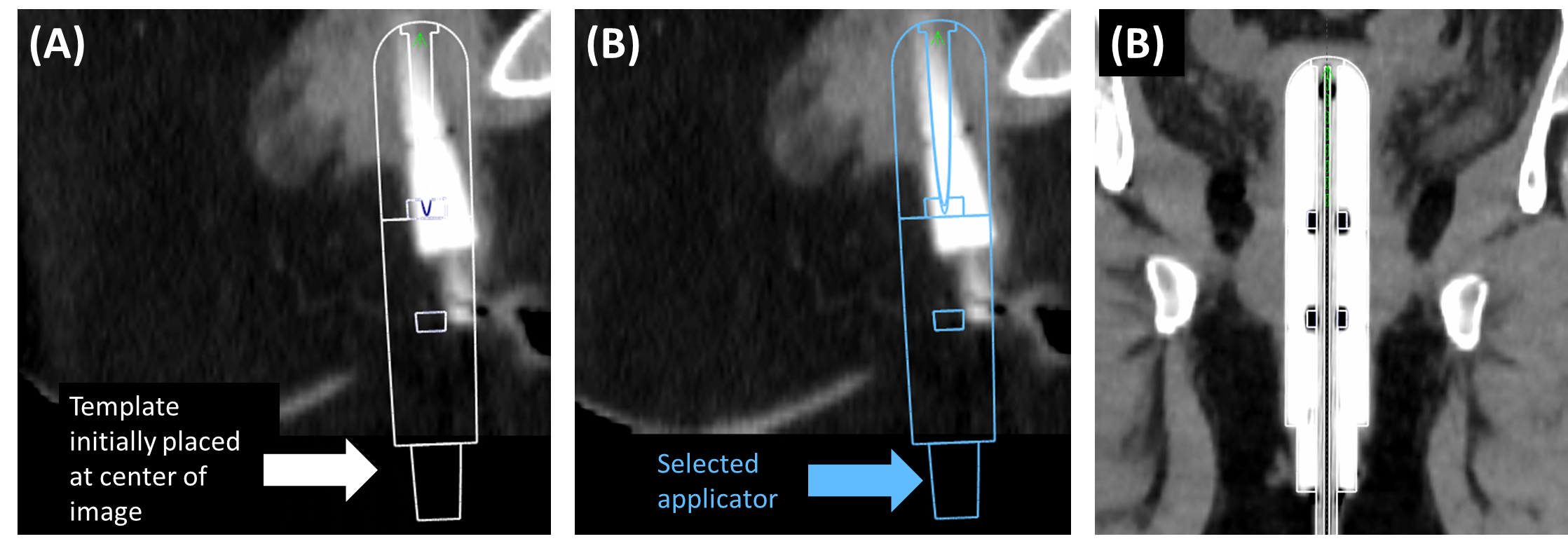
19. Align Template with CT
- Click applicator to select
 (turns blue when selected)
 - Use
Move applicator and
and Rotate applicator tools
tools - Align template with CT-visible cylinder
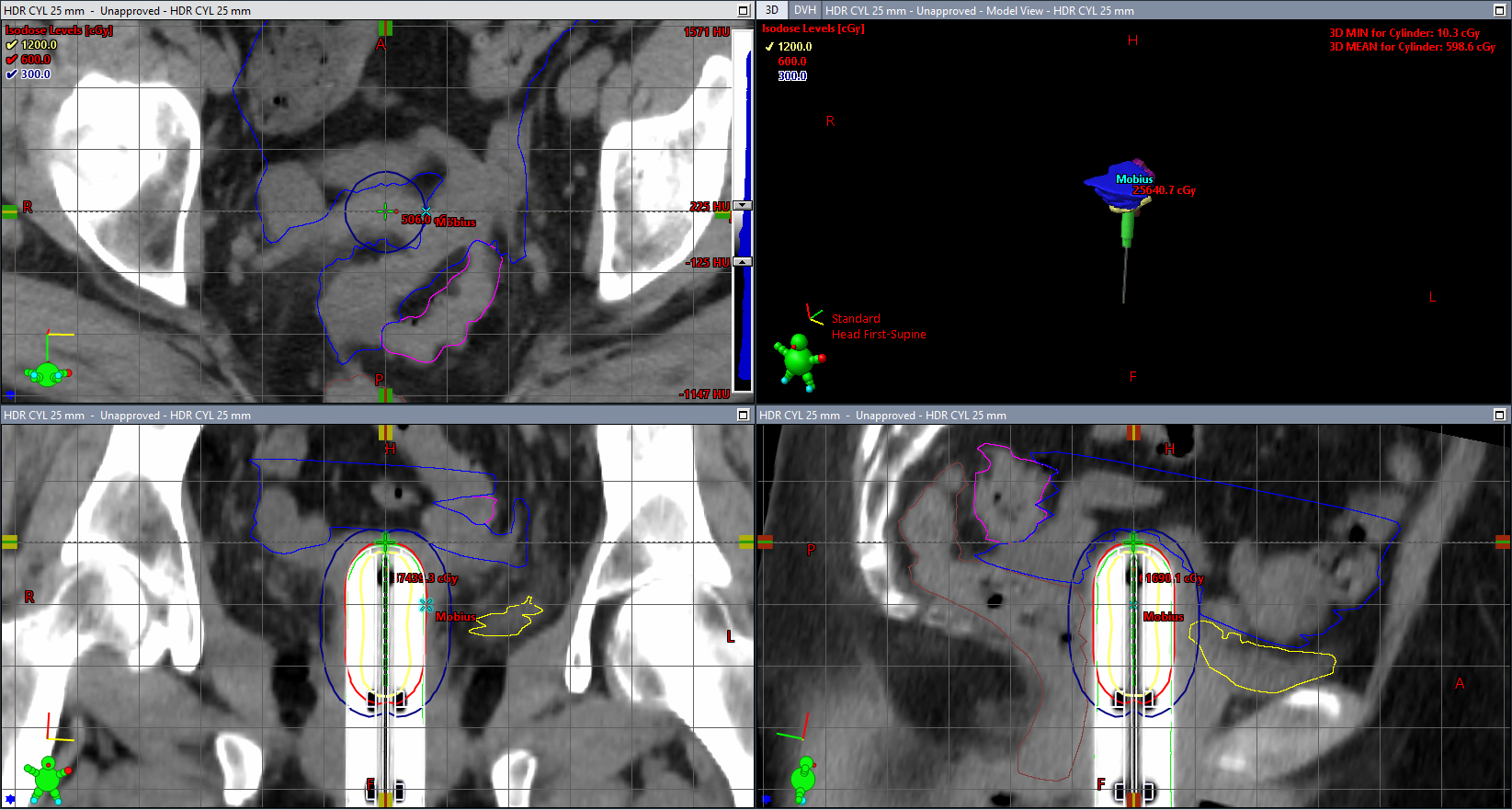
3.5 Configure Dose Display
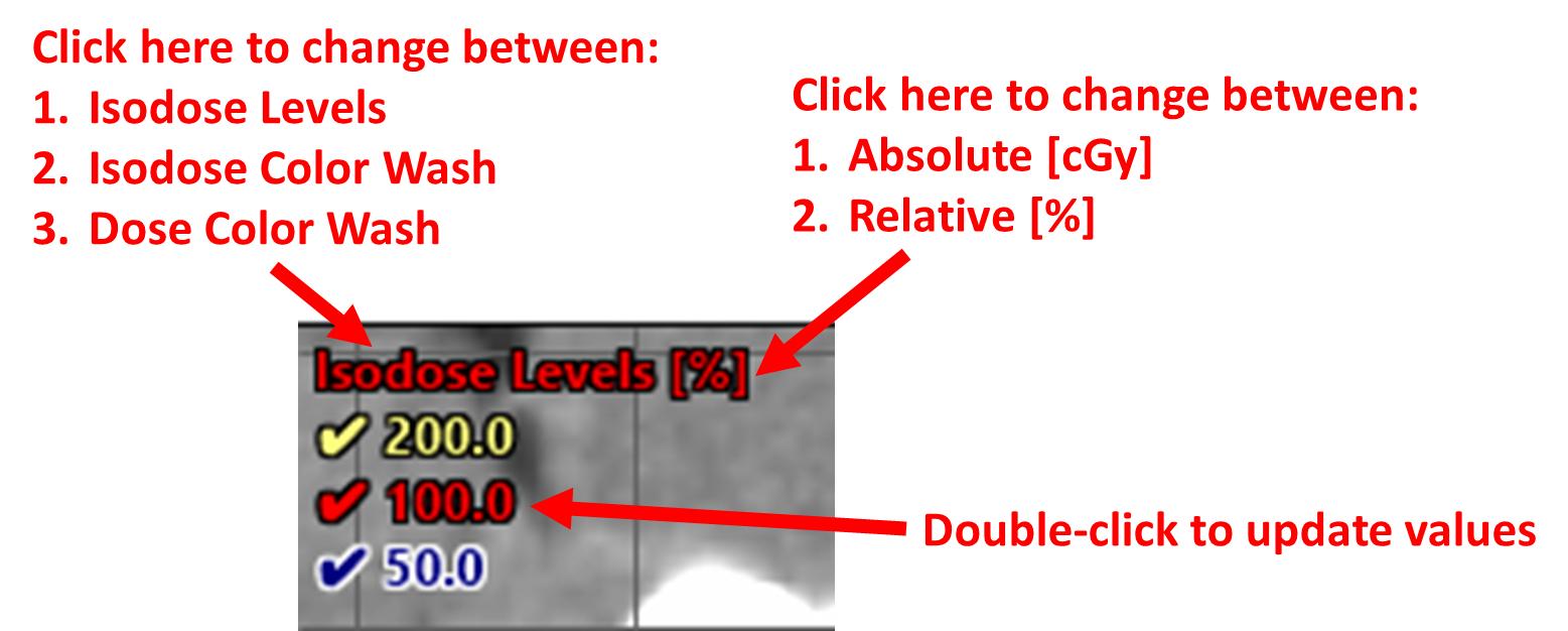
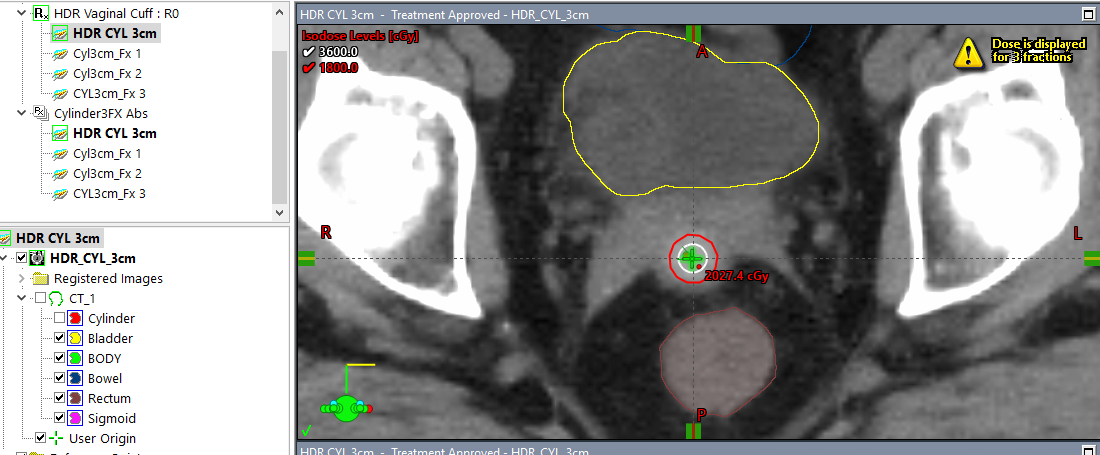
20. Set Isodose Levels (Choose preferred option)
Option A (Three levels):
- Click elements on top left corner of axial plane
- 200% = Yellow
- 100% = Red
- 50% = Blue
- Units: Set to absolute by clicking
[%]symbol so it becomes[cGy]
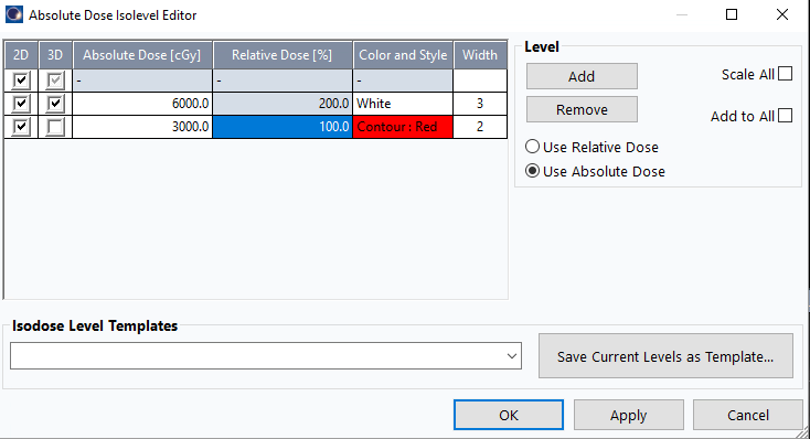
Option B (Two levels):
- Right-click
Dose > Uncheck
 Absolute Dose(if checked) - Right-click
Doseagain >Isodose Levels - Keep only 100% (red) and 200% (white) checked in 2D and 3D
Apply>OK
3.6 Set User Origin and Default Views
21. Position Crosshairs
- Move sagittal and coronal crosshairs so planes run along cylinder central axis
- Move axial plane to 3 mm (one slice) above cylinder tip
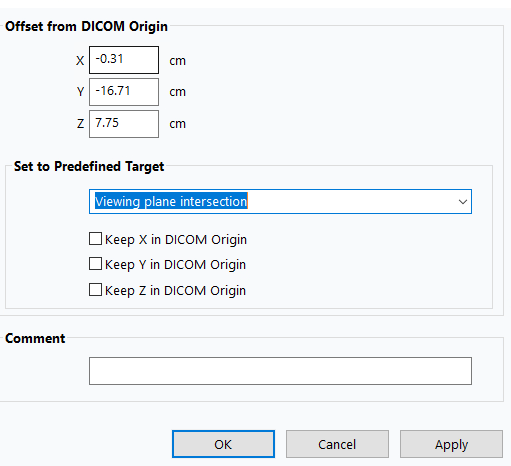
22. Set User Origin
- Right-click
User Origin >
> Set User Origin - Under
Set to Predefined Target:Viewing Plane Intersections>Apply>OK
Double-click User Origin icon to return to this position, or right-click and select 'Move Viewing Planes To User Origin'.
23. Set Default Viewing Planes
- Return to
User Origin - Zoom out to display entire dose distribution
- Click
Set Default Viewing Planes button
 Set to Current>OK
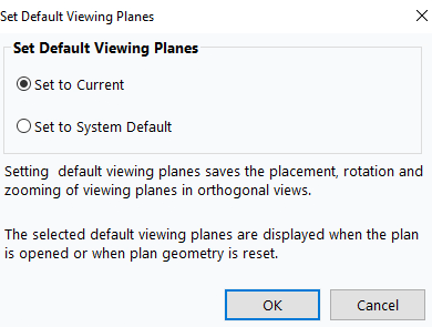
- Click
Reset Geometry to return to this setup
Ensure cylinder is positioned high enough in view to show complete dose curves.
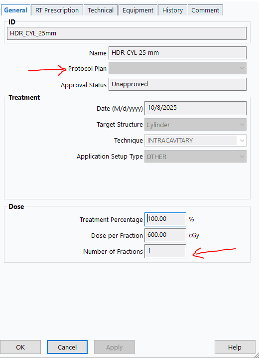
3.7 Add Clinical Goals
24. Configure Plan for Single Fraction
- Verify plan properties show no
Protocol Plan - Confirm Number of fractions:
1
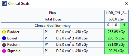
25. Load Clinical Goals
Planning>Add or Edit Clinical Goals...- In
Clinical Goal Templates, find and selectHDR Cylinder Dunn_1Fx
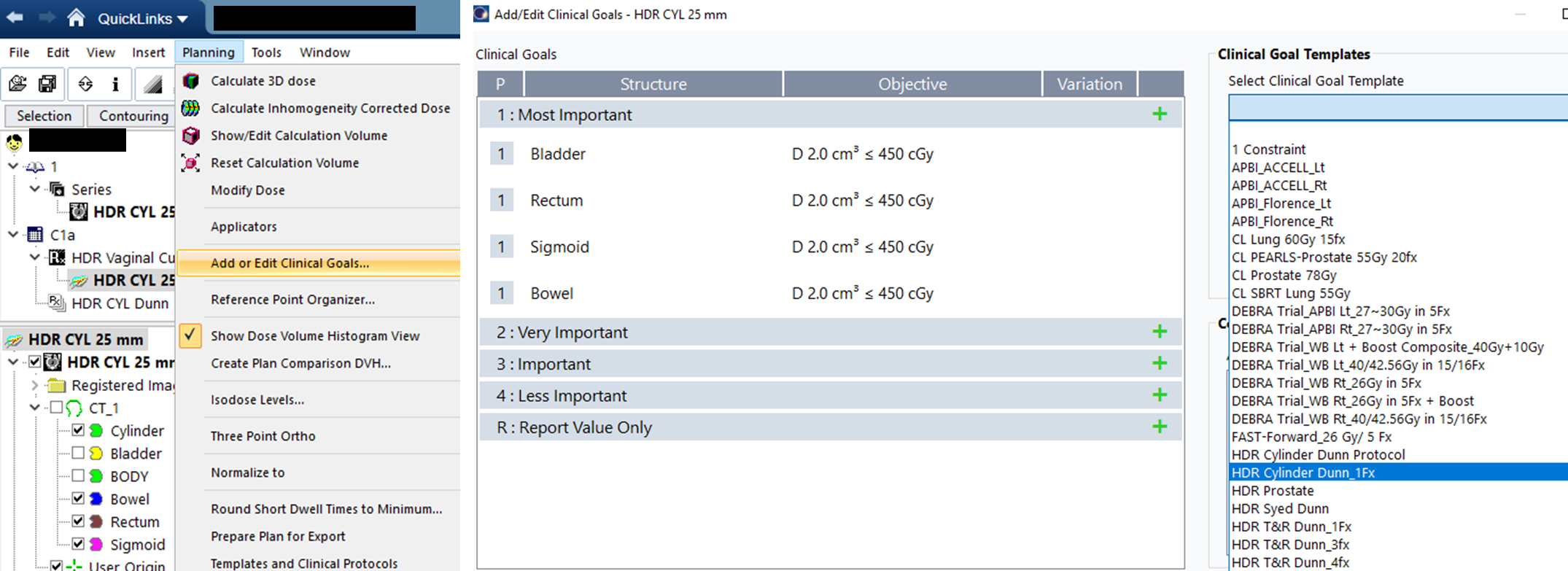
26. Verify Goals
- Right-click top right window >
Show Dose Volume Histogram View Dose Statisticstab: Check all OARs (except body) for DVH displayPlan Objectivestab: Confirm all goals are green/passing
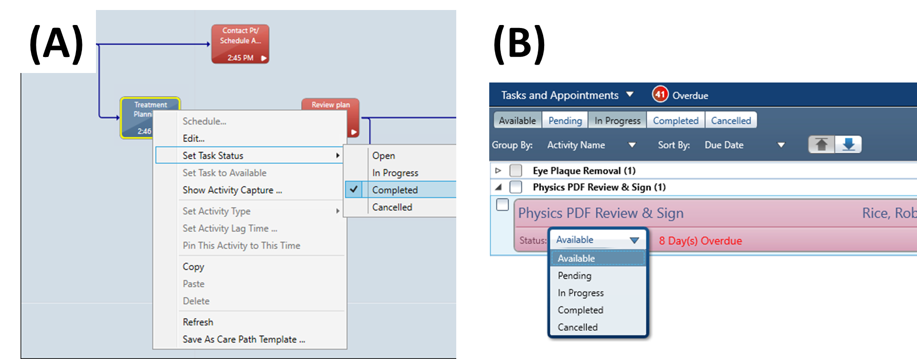
27. Complete Treatment Planning Task
- Option A:
QuickLinks>EMR>Care Path> Right-click task >Completed - Option B: Check Tasks in Aria > Change Physics-Brachy status to
Completed
Plan is now ready for physician review and approval/modification.
4. Mobius Secondary Calculation
4.1 Create Reference Point
28. Position Reference Point
- Double-click
User Originicon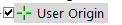
- On coronal slice, align sagittal crosshairs with cylinder edge
- Use
Measure Distancetool : Measure 2 cm down/inferior from user origin
 - Move crosshairs to cylinder surface at this distance
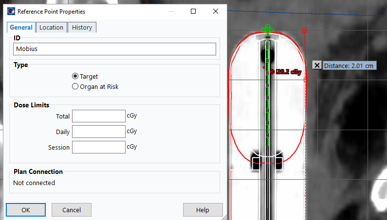
29. Create Mobius Point
- Right-click
Reference Points>New Reference Point And Location - Click anywhere on images
- Name:
Mobius - Type:
Target OK
30. Position Point Precisely
- On coronal plane, move horizontal (axial) and vertical (sagittal) plane indicators to intersect cylinder side
- Right-click
Mobius>Move Reference Point To Viewing Planes Intersection
4.2 Export to Mobius
31. Send Plan to Mobius
- Right-click plan name (e.g.,
HDR_CYL_3cm) >Export>Mobius3D - Server 3 - Click blue arrow
 (left corner) >
 Authorize - Verify all files transferred successfully

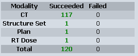
Ensure number of fractions is set to 1 before export.
You need server account credentials. Confirm current recommended server with senior staff.
Mobius Server IPs:
| Server Name | IP Address |
|---|---|
| Mobius Server 1 | 10.177.8.43 |
| Mobius Server 2 | 10.177.8.70 |
| Mobius Server 3 | 10.110.16.21 |
5. Post-Planning Documentation
5.1 Mobius Verification
32. Access Mobius Report
- Navigate to Mobius Server (IP:
10.110.16.21) - Log in with credentials
- Click patient name >
Open PDF Report(third icon from left)
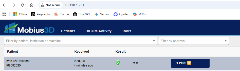
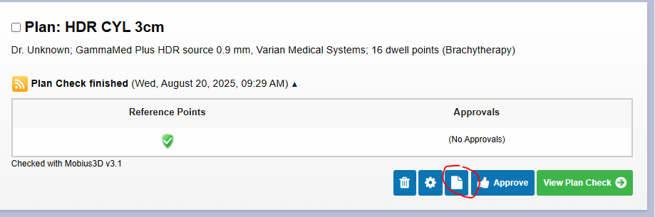
33. Verify Agreement
- Scroll to bottom of plan data
- Confirm percent difference shows green checkmark (Mobius 2nd Check & Eclipse agree within tolerance)
- Save report to P-drive as
4-mobius - Path:
P:\1. Methodist Dunn\3B. HDR Bravos Dunn\1. HDR Patient QA
34. Clean Up
- Return to Eclipse plan
- Delete
Mobiusreference point
Mobius point only needed for calculation documentation; removing improves screenshot clarity.
5.2 Generate Eclipse Documentation
Reset number of fractions in plan properties to full amount (3 or 5) before generating documentation.
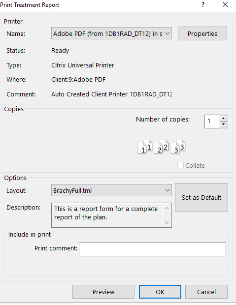
35. Create Plan Report
File>Print>Report- Printer:
Adobe PDF - Layout:
BrachyFull.tml OK- Save to patient path as
1-report
36. Create DVH Report
Dose Statisticstab: Check all structures for DVH display- Click DVH panel (top right)
- Right-click >
Print DVH Report>OK - Save to patient path as
3-dvh
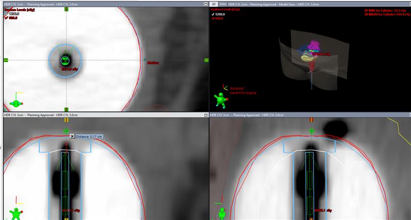
37. Create Orthogonal Views Screenshot
- Double-click
User Origin - Display
Clinical Goalstab in bottom panel File>Print>ScreenProperties>Layout: Change toLandscape- Save as
2-iso
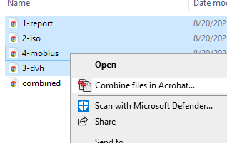
38. Combine Documents
- Select all files (1-report, 2-iso, 3-dvh, 4-mobius)
- Right-click >
Combine files in Acrobat
5.3 Create Imaging Course
39. Add New Course
QuickLinks>Treatment Planning>External Beam PlanningInsert>New Course...- Name:
C1a-Imaging(orC2a-Imagingfor second brachytherapy course)
40. Create Imaging Plan
Insert>New Plan from Template...>DunnBravosSU>Next- Select
C1a-Imagingcourse >Next - Treatment unit:
Omega>Next - Keep default dose settings >
Next - Target:
Cylinderor checkNo plan target - Primary reference point:
User Origin>Next - Isocenter placement:
At image origin>Next - Patient position:
Head First-Supine
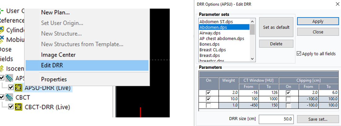
41. Configure DRR
- Right-click DRR icon >
Edit DRR - Select
Abdomen.dps - Check
Apply to all fields>Apply
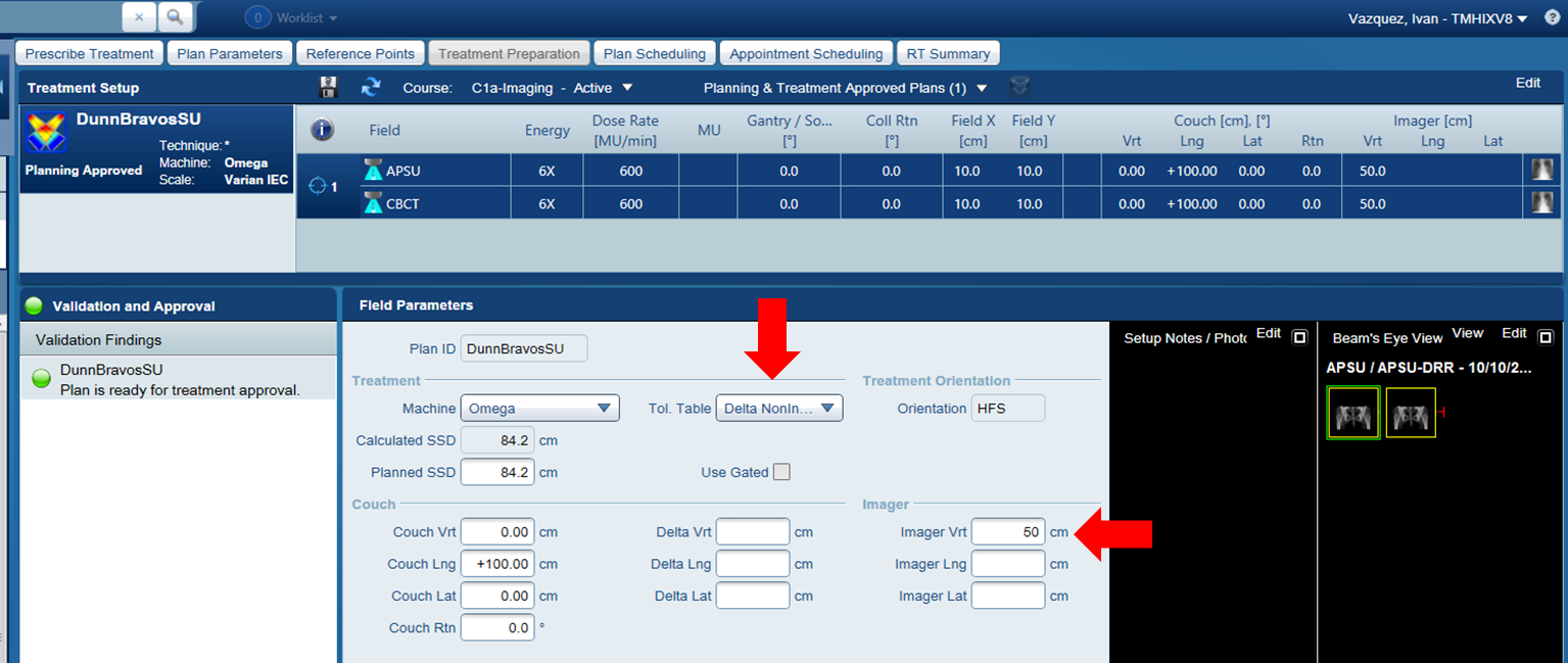
42. Set Treatment Parameters
QuickLinks>Treatment Management>Treatment Preparation- Tolerance table:
Non-Index - Imager Vrt:
50.0 cm
5.4 Configure Dose Limits
43. Set Reference Point Limits
- Return to
Brachytherapy Planning - Double-click reference point (
Cylinder,CTV, etc.) - In
Dose Limitssection:- Total: (Number of fractions × 600 cGy)
- Daily Dose Limit:
600 cGy(or1200 cGyfor BID regime) - Session Dose Limit:
600 cGy
Apply>OK
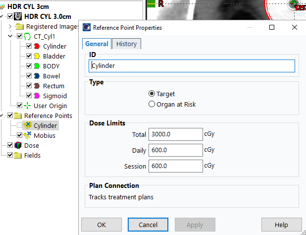
Dose limits enable plan approval and allow dosimetry monitoring across fractions. Without this, planning approval will show warnings about inability to monitor plan dosimetry.
5.5 Approve Plans
44. Approve HDR Plan
- Right-click plan >
Plan Approval>Planning Approved - Acknowledge minor warnings (unapproved/rejected structures)
- Enter credentials for verification
Blue box = Planning Approved. Green box = Treatment Approved (appears later).
45. Approve Imaging Course
- Right-click
DunnBravosSU plan>Plan Approval>Planning Approved>Next - Check
Continue planning approval without calculating dose and/or MUs - Continue until prompted for password
6. Import Documents to Aria
6.1 Upload Combined Plan Document
46. Import Combined PDF
Quicklinks>Documents- Click
Import(NOT "New") - Select combined PDF from patient folder
47. Configure Document Properties
- Authored By: Your name
- Supervised By: Dr. Farach (or treating physician)
- Document Type:
Treatment Plan - Initial - Template Name:
HDR Cylinder
UNCHECK 'Completed' to prevent premature physician sign-off before physics approval.
48. Save Document
- Click
OK(NOTSign Off)
6.2 Additional Documents (First Planning Only)
Complete steps 49–51 only if this is the patient's first planning session.
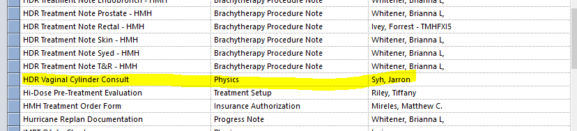
6.2.1 HDR Vaginal Cylinder Consult
49. Create Consult Document
Quicklinks>Documents>New- Click
Template> CheckShow All Templates - Select
HDR Vaginal Cylinder Consult>OK - Supervisor: Physician name
- UNCHECK 'Completed'
If HDR Vaginal Cylinder Consult is unavailable, verify correct institution (HMH) is selected.
50. Complete Template Fields
- Treatment Length:
4 cm(standard for Dr. Farach) - Diameter of Cylinder: X cm (measured value)
- Dose to Depth:
600 cGy to depth of 0.0 cm - D2cc Bladder: ___ cGy (from Plan-COMBO PDF ÷ 5)
- D2cc Rectum: ___ cGy (from Plan-COMBO PDF ÷ 5)
- Click
OK(NOTSign Off)
If physician modifies isodose lines during review: recalculate dose, regenerate all documents, re-upload combined PDF, and update doses in this document.
6.2.2 Treatment Plan Note
51. Create HDR Treatment Plan Note
New>Template> CheckShow All Templates- Select
Tx Plan HDR Note - HMH>OK - Supervisor: Physician name
- UNCHECK 'Completed'
- Complete fields:
- Plan type:
3D Plan(because CT-Sim is used as basis) - Number of Channels:
1(only 1 channel in cylinder) - Number of Basic Dosimetry Calculations:
1(secondary calculation via Mobius with one reference point)
- Plan type:
- Click
OK(NOTSign Off)
7. Scheduling and Billing
7.1 Schedule Treatment
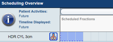
52. Schedule Fractions
Quicklinks>Treatment Management>Plan Scheduling- In
Scheduling Overviewpanel: Shift+Click+Drag across boxes equal to number of fractions - Click
Insertto add blue treatment blocks - Click
Saveicon
7.2 Billing
Skip billing steps if only practicing plan creation.
53. Open Charge Manual
- Location:
Physics Drive > 1. Methodist Dunn > HDR Main > Charge Manual
- Navigate to
HDR Vaginal Cylindersheet - Note all
CPTcodes inPlan Daysection withPHYas responsible party
54. Access EMR Summary
Quicklinks>EMR>Summary- Click
Taskstab
55. Create Prepare Plan Task
- Click
Newbutton
- Activity: Select
Prepare Planfrom dropdown
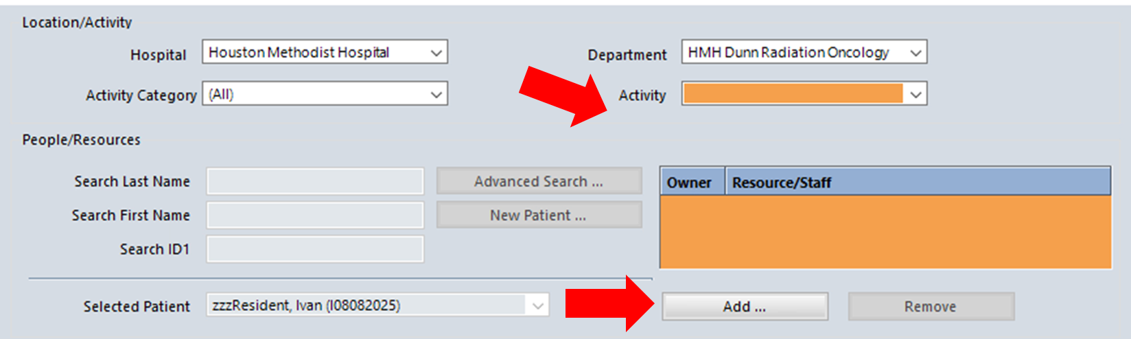
56. Add Physics Staff
- Click
Addbelow Activity box - Find and highlight
Physicsin Resource/Staff menu
- Add to right side
- In Staff list below, find your name and add to right side
- Check your name >
OK
57. Complete and Capture Task
- Set Status:
Completed
- Click
OKat bottom of Task Dialog - Back in Tasks tab, scroll to
Prepare Planactivity - Right-click >
Activity Capture!
58. Add Billing Codes
- Click
Add More Procedure Codes - Check
Show All Procedure Codes - Add all codes from Step 53
- Special note: If CT-Sim used, check
77295INSTEAD of7731Xcodes - Click
Save Edits
8. Subsequent Fractions
8.1 Create Decay-Corrected Plans
59. Copy Plan for Next Fraction
Quicklinks>Treatment Planning>Brachytherapy Planning- Open course
- Right-click PLAN (e.g.,
HDR_CYL___cm) >Copy Plan - Right-click COURSE (e.g.,
C1a) >Paste Plan
60. Rename Plan
- Plan ID:
Cylfx___(fill in fraction number) - Example:
Cylfx2,Cylfx3, etc.
61. Adjust Plan Date
- Open plan properties
- Update date to match scheduled treatment date
- Ensures correct source decay calculation
8.2 Generate Decay Calculation Report
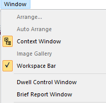
62. Create Brief Report
Window>Brief Report Window- Press
Ctrl+P - Printer:
Microsoft Print to PDF OK- Save as:
DecayCalc_CYL_XXmm_FxN - Example:
DecayCalc_CYL_25mm_Fx2
8.3 Upload Fraction Reports
63. Import on Treatment Day
- On day of treatment:
Quicklinks>EMR>Documents - Click
Import - Select
DecayCalc_CYL_XXmm_FxNfrom patient folder - Click
Open
64. Configure Document Properties
- Authored By: Your name
- Supervised By: Dr. Farach
- Document Type:
Treatment Plan - Decay Calc - Template Name:
Cylinder Fx___ - UNCHECK 'Completed'
- Click
OK(NOTSign Off)
Appendix A: Keyboard Shortcuts
| Action | Shortcut |
|---|---|
| Reload all | Alt+F, R |
| Switch contouring tools | Right-click to highlight, then select |
| Window level adjustment | Shift + Move Mouse |
| Auto window level | Alt+V, A |
| Create structure | Alt+S, Enter |
| Fill structure info | Down, Tab, type name, Enter |
| Rotate plane views | Ctrl+R |
| Blend fusion | Ctrl+A |
| Skip slices | Alt+Mouse Wheel |
| Delete contour | Select Pencil, Delete |
| Hide all except selected | Hold H |
| Show/hide in adjacent slices | Alt+V, S, Enter |
| Toggle 2D/3D brush | 2 |
| Toggle static/adaptive brush | A |
| Brush as eraser | Hold Shift |
| Adjust brush diameter | Right-click and drag left/right |
| Copy/paste contours | Ctrl+C, Ctrl+V |
Appendix B: Manual Planning (Training Only)
This method is for educational purposes. Use template-based workflow for clinical cases.
B.1 Orient Cylinder and Set User Origin
1. Orient Cylinder (see Section 3.4)
- Rotate sagittal and coronal planes to ensure cylinder is roughly vertical
- Define user origin at tip of applicator
B.2 Manual Plan Creation
2. Insert Plan Manually
- Select course >
Insert>New Plan - Click
Nextwith course highlighted - Highlight treatment prescription > Check
Select>Next - Highlight cylinder as target >
Next
3. Configure Plan Properties
- ID & Name:
HDR Cyl___cm - Protocol Plan:
Cylinder Dunn\Cylinder - Target Volume:
Cylinder - Technique:
Intracavitary - Treatment Percentage:
100% - Dose per Fraction:
600 cGy - Number of Fractions:
5 - Click
OK
B.3 Insert Applicator
4. Add Applicator
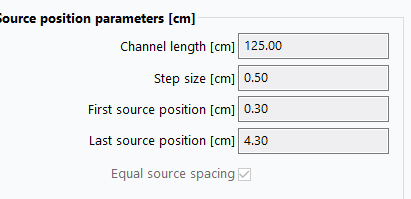
Insert>New Applicator>Bravos - Dunn- Configure Applicator Properties:
- Channel Length:
125cm (always for HMH cylinders) - Step Size:
0.5cm - 1st Source Position:
0.3cm - Last Source Position:
4.3cm
- Channel Length:
- Click
OK
B.4 Digitize Applicator
Method 1: Two-Point Method
5. Draw Applicator
- After inserting applicator, drawing button
 becomes active
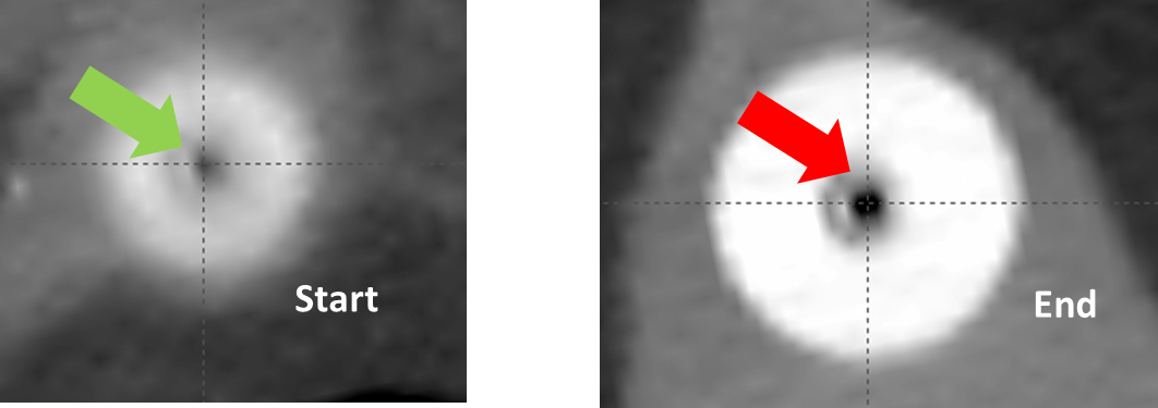
 - Navigate to cylinder tip in axial view (where low intensity cavity vanishes)
- Click at center of channel (defines end of source positions)
- Move inferiorly to applicator base
- Click at center of channel (defines start)
Method 2: Multi-Point Method
- Ensure proper rotation (channel vertical)
- Use
Contour Editorbutton - Click multiple points along central channel from base to tip
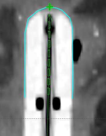
B.5 Create Reference Line
6. Add Reference Line
- Highlight CT study (e.g.,
CT_1) Insert>New Reference Line>OK- On coronal plane containing User Origin:
- Click along cylinder surface from one side to other
- Position at level of last dwell position
- Click
Selection Tool to exit reference line mode
B.6 Initial Dose Calculation
7. Run Volume Optimization
Planning>Modify Dose>VEGO TG-43 Volume Optimization- Click
OKat normal tissue structure creation prompt
8. Configure Optimization
- Set Smoothness: Middle of meter (Top High = Coarse, Top Low = Finer DVH)
- Create objectives:
- Highlight
Reference Line - Click
Add Upper & Lower Objective
- Desired dose:
3000 cGy(prescription amount per fraction) >OK
- Highlight
9. Set Lower Objective
- Volume:
99% - Dose:
3000 cGy(100%) - Priority:
100
10. Set Upper Objective
- Volume:
1% - Dose:
3005 cGy(100.17%) - Priority:
100
11. Optimize and Calculate
- Click
Optimize - Click
Calculate 3D dosebutton
B.7 Modify Isodose Display
12. Set Isodose Levels (see Section 3.5)
B.8 Dose Shaping
13. Shape Dose Distribution
- Click
Dose Shapertool
- Right-click in views >
Dose Shaping Effect> SelectLocal>OK - On frontal/sagittal views: Ctrl+Drag near 100% red isodose line
- Shape onto cylinder surface
Use Dose Re-Scaler if dose shape is correct but not aligned. This allows proportional scaling of dwell times while retaining shape.
14. Save Plan
Appendix C: Troubleshooting
Common Issue: Improper Template Positioning
Problem: Template positioned inferior to correct location
Identification:
- End of digitized channel does not coincide with end of channel cavity
- Low attenuation region in cylinder center misaligned
Solution:
- Use
Move applicatortool to reposition template - Align digitized channel end with visible cavity end
- Verify alignment in all three planes