Verify source positioning, dwell time accuracy, and proper function of the afterloader to guarantee safe, precise delivery of treatment and ensure patient and personnel safety. After completion, the physicist will have confirmed that all safety features in the treatment and control rooms function properly.
Phase 1. Control Room Setup
1.1 Initial Power-Up and System Checks
1. Power On Equipment
- Ensure the wall switch is set to
HDR - Turn on all cameras and scan the room to verify
Video Monitor/Intercomare functional
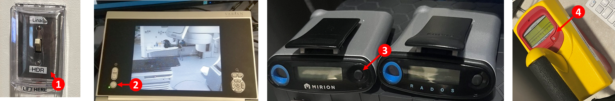
2. Activate Safety Monitors
- Turn on the personal dose monitor by holding down the power button
- Turn on the radiation survey meter
3. Console System Check
- Locate the console key and switch the system on
- Note the following displayed information:
- Date and time (verifies
Date/Time on Console Correct) - Source activity/strength
- Battery level (UPS Status should be > 90%)
- Date and time (verifies
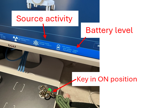
Record the source activity for TotalQA logging. Take a picture before leaving the control room if you plan to fill out the report elsewhere.
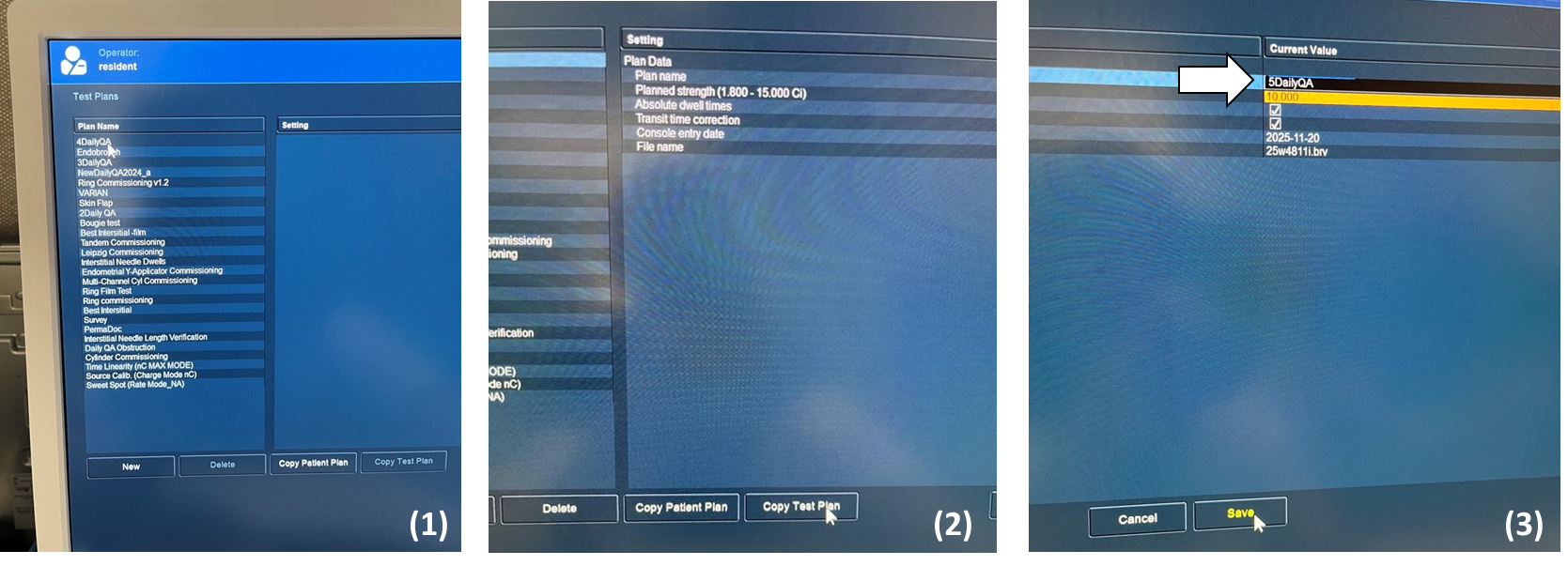
1.2 Prepare Test Plan
4. Log In and Load Test Plan
- Log in with your clinic-approved credentials
- Click
Test Plans>4DailyQAand proceed
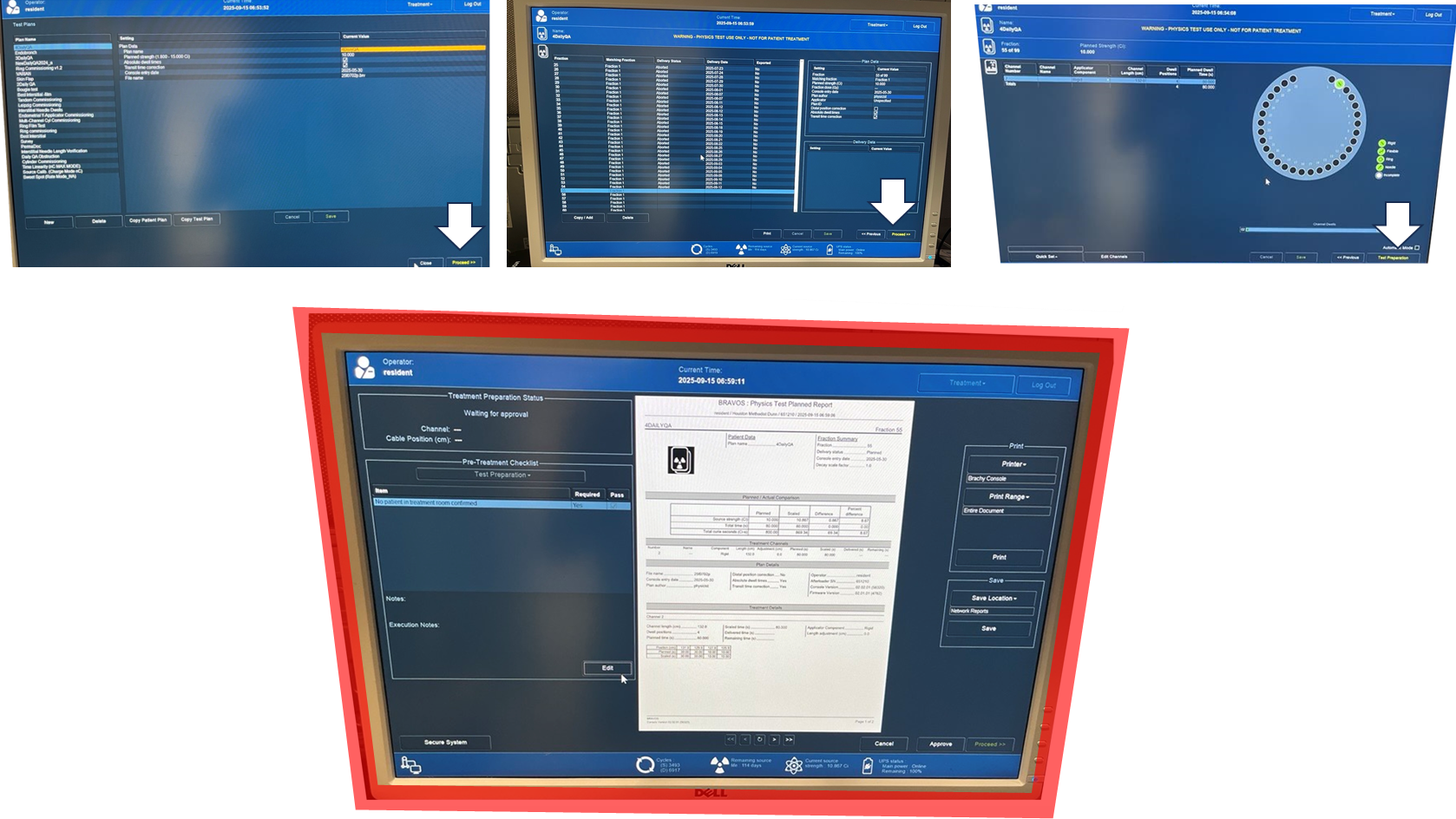
The number prefix (e.g., "4") increments after the maximum fractions (n = 99) are delivered. When the current plan is exhausted, create a copy with the next ascending number (see Section 4 below).
Phase 2. Treatment Room Setup
2.1 Enter Room and Initial Setup
5. Enter Treatment Room Safely
- Enter with the survey meter every time
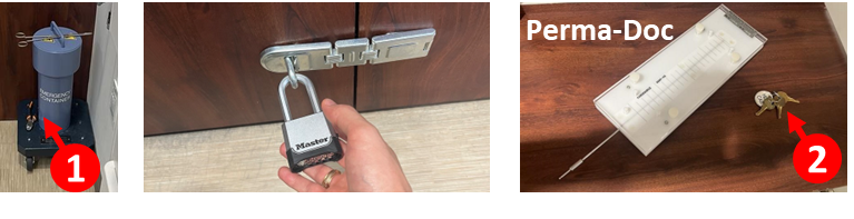
- Verify the emergency container ("lead pig") is present in the room
6. Access Equipment
- Retrieve the lock key and Perma-Doc from the cabinet
- Unlock the two exterior locks on the cabinet using the current clinic-approved access process
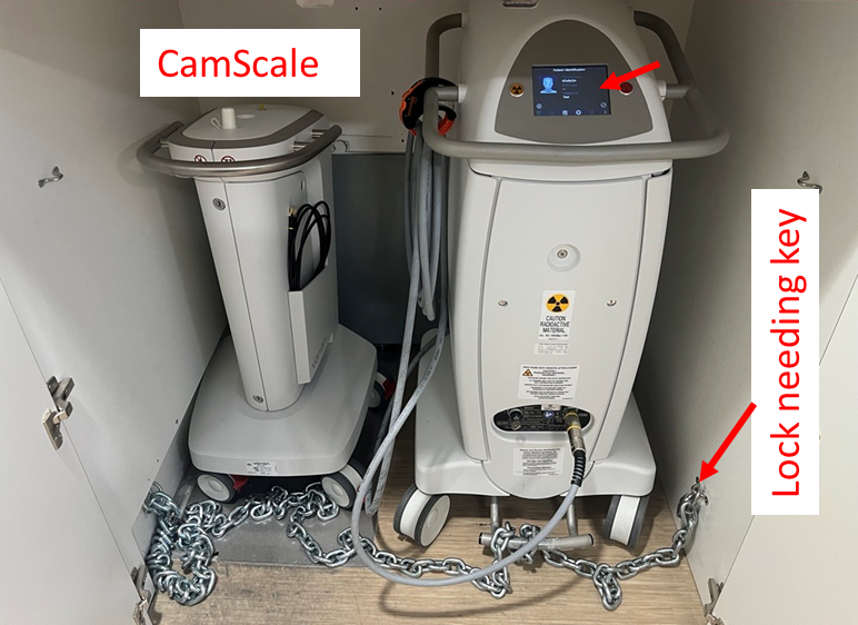
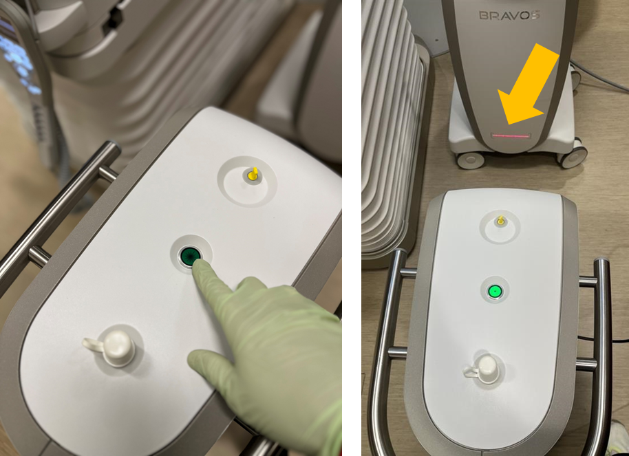
7. Unlock Afterloader
- Use the key to unlock the afterloader's lock and remove the chain
- Verify the test plan information appears on the afterloader display (indicated by arrow)
2.2 Position Equipment
8. Position CamScale
- Roll out the CamScale and position it in line with the treatment bed facing the gantry
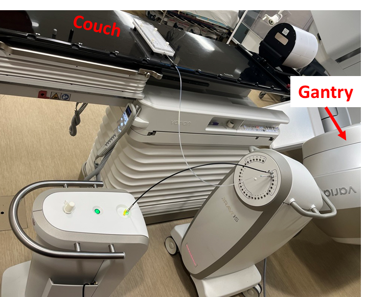
9. Position Afterloader
- Roll out the afterloader in front of the CamScale
- Position it parallel to the couch, on the side closer to the gantry
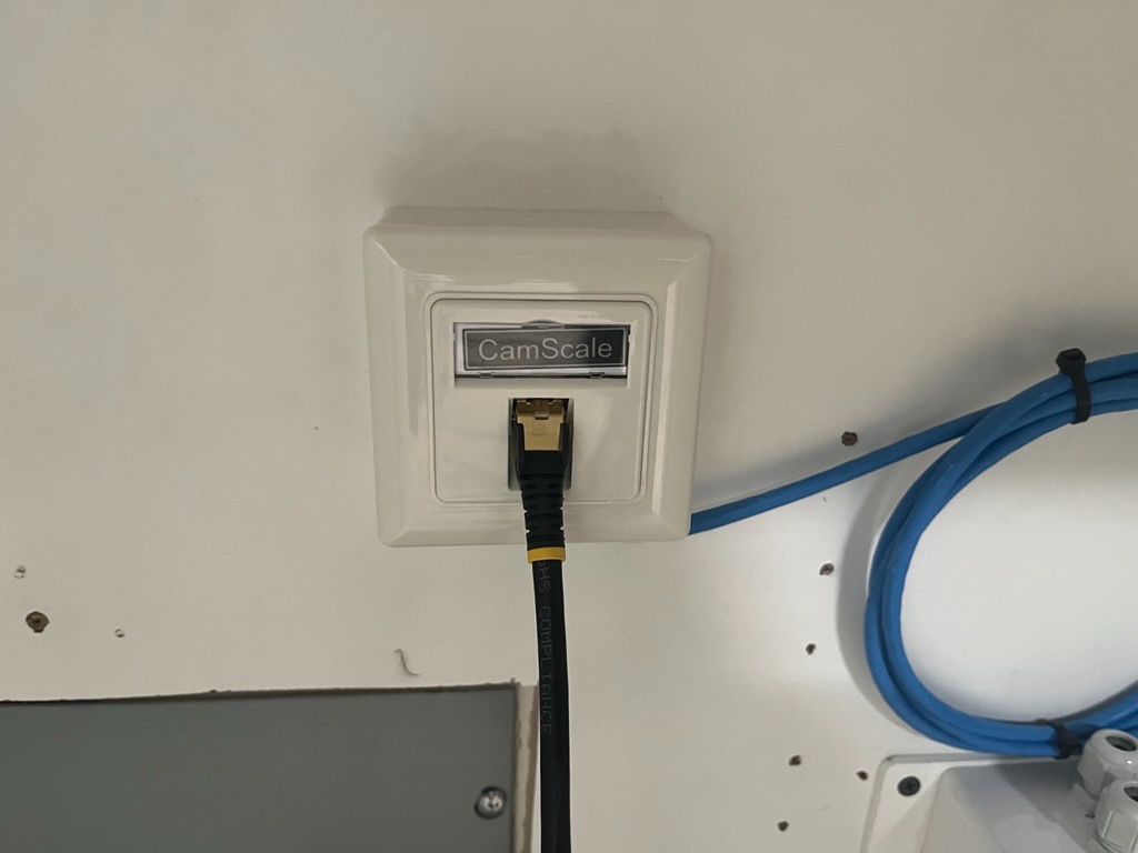
10. Connect CamScale Network
- Connect the CamScale ethernet cable to the wall port inside storage
11. Align CamScale
- Align the CamScale so the laser line remains within the tolerance region marked on the afterloader
Maintain a consistent setup position. CamScale results can fluctuate based on positional differences between the afterloader and CamScale.
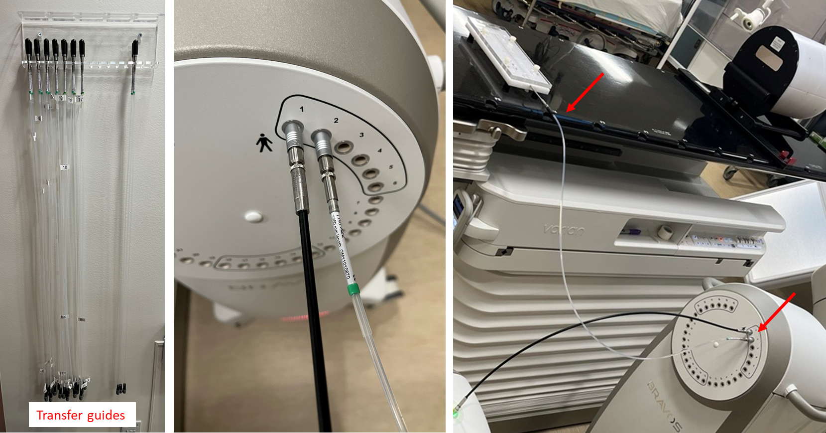
2.3 Connect Transfer Guides
12. Connect Channel 1 (CamScale)
- Connect the transfer tube from CamScale storage (black tube) to the CamScale
- Connect the other end to channel 1 of the afterloader
Do not flip the CamScale transfer guide. The top end of the tube connects to the afterloader; the bottom end connects to the CamScale.
13. Connect Channel 2 (Perma-Doc)
- Connect the transfer guide from the wall rack to the Perma-Doc
- Connect the other end to channel 2 of the afterloader
Phase 3. Safety Checks
3.1 Length Verification
14. Run Length Measurement
- With the plan loaded on the afterloader, run
Length Measurement - Tolerance: 132 cm ± 1 mm
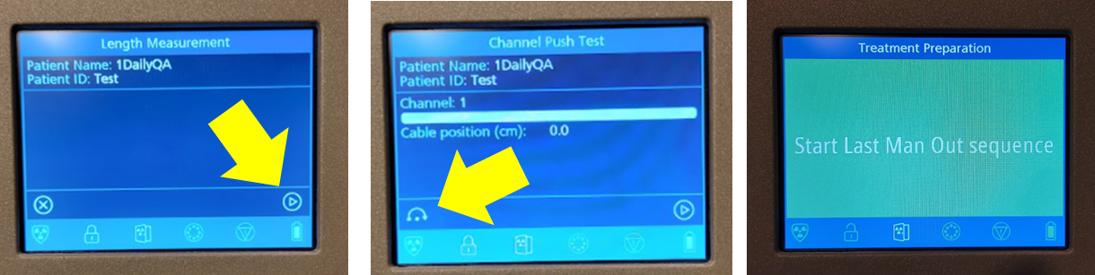
15. Skip Push Test
- Press the skip button when prompted for
Push Test
If the test plan was not prepared in the control room, return and complete step 4 before continuing.
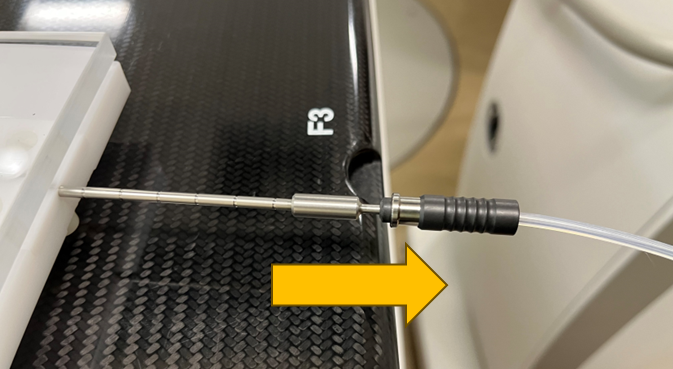
3.2 Obstruction Detection Test
16. Prepare for Obstruction Test
- Partially disconnect the transfer guide from the Perma-Doc (leave it loose)
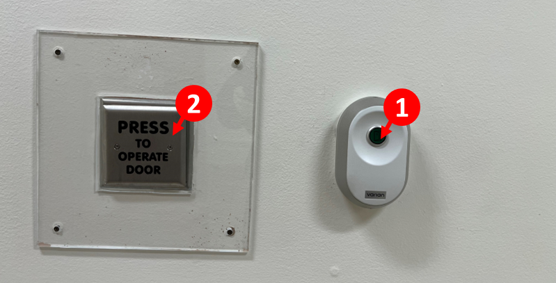
17. Exit Room
- Start the
Last Man Outsequence on the way out (press 1, then 2)
18. Complete Pre-Treatment Checklist
- Complete the
Pre-treatment checklistat the console - Click
Done>Approve
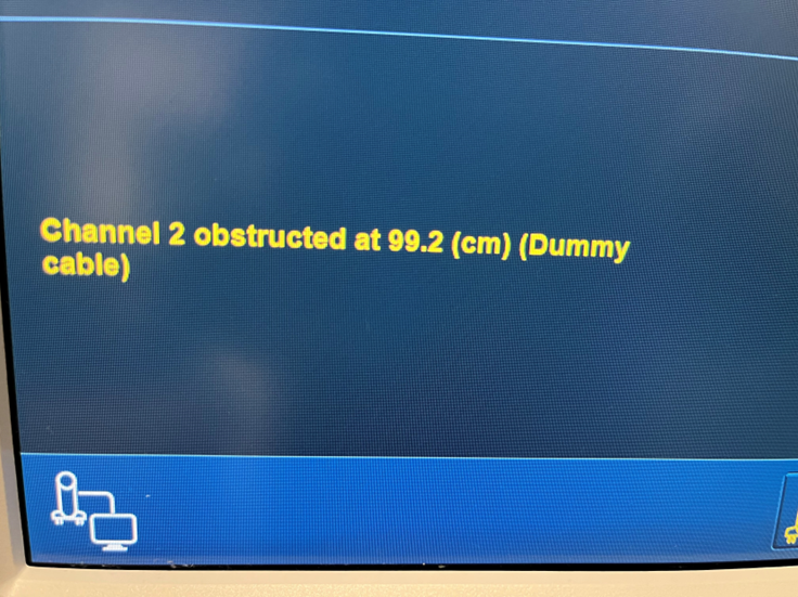
19. Run QA Plan
- Run the QA plan from the control room
- The system should detect the obstruction in channel 2, confirming that obstruction detection is working
20. Reconnect Transfer Guide
- Return to the room
- Properly connect the transfer guide to the Perma-Doc
- Restart the
Last Man Outsequence on exit
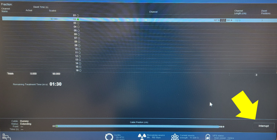
3.3 Dwell Time and PrimAlert Verification
21. Run QA Plan with Proper Connections
- Run the QA plan from the control room with the transfer guide properly connected
22. Time First Dwell Position
- Start both timers when the source (yellow indicator) reaches the first dwell position

- Expected dwell time: 30 seconds
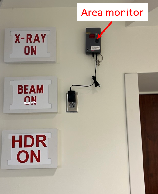
- While timing, visually inspect that the PrimAlert monitor is blinking
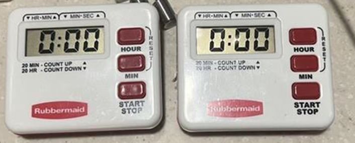
23. Stop Timers
- Stop the timers when the source leaves the first dwell position
- Both timers should read 30 seconds
3.4 Interrupt Button Test
24. Test Console Interrupt
- Click the
Interruptbutton on the graphical interface after the source leaves the first dwell position - This should:
- Interrupt treatment
- Park the source
- Turn off the PrimAlert monitor lights
3.5 Key Interlock Test
25. Test Key Interlock
- Restart delivery of the QA plan
- Wait for the source to reach a dwell position
- Turn the key to the middle position to interrupt treatment
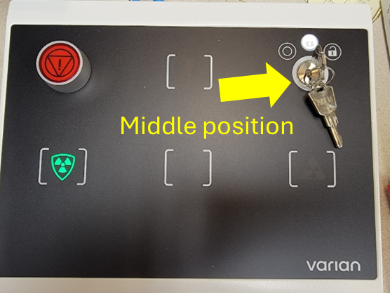
Turning the key fully to the OFF position will terminate the test and require a repeat of all interruption checks. Use the middle position only.
3.6 Door Interlock Test
26. Test Door Interlock
- Restart delivery of the QA plan
- Wait for the source to reach a dwell position
- Open the vault door while the source is out — treatment should interrupt
- Restart the
Last Man Outsequence
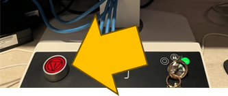
3.7 Emergency Stop Test
27. Test Emergency Stop Button
- Restart delivery of the QA plan
- Wait for the source to reach a dwell position
- Press the Interrupt (red) button on the console to halt treatment
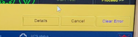
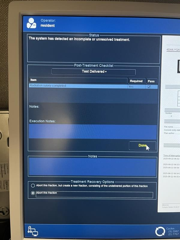
28. Clear Error and Complete
- Click
Clear Error - Move to the next screen to sign off on the tests
29. Abort Fraction
- Select
Abort this fractionbefore clickingDone
3.8 Source Position Verification
30. Access Position Verification
- Click the dropdown menu (top right, to the left of
Log Out) - Select
System Configuration>Cable and Source>Proceed
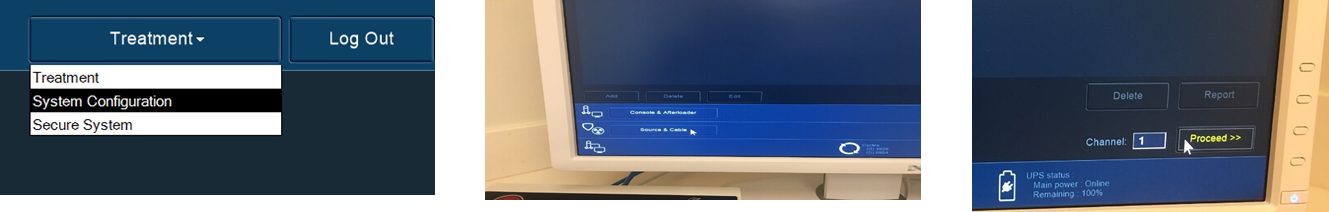
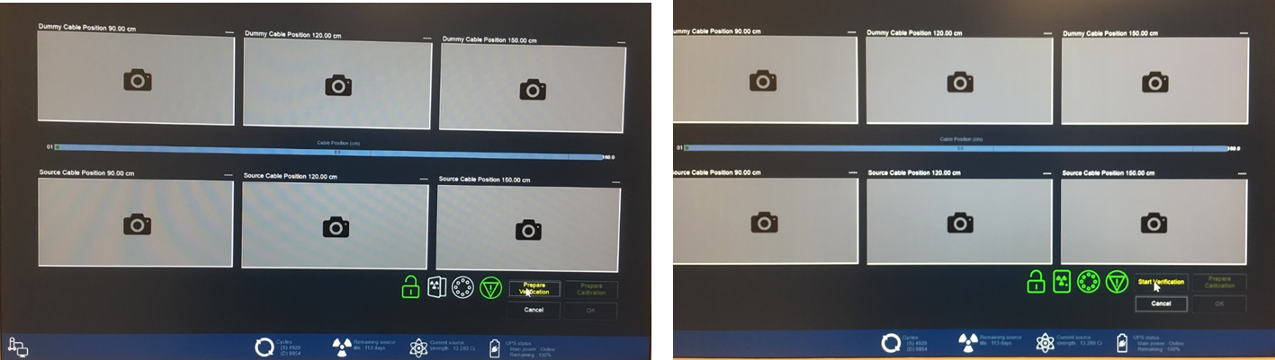
31. Run Position Verification
- Ensure the
Position Verificationtab is selected - Proceed until reaching the verification window
- Click
Prepare Verificationand run the check
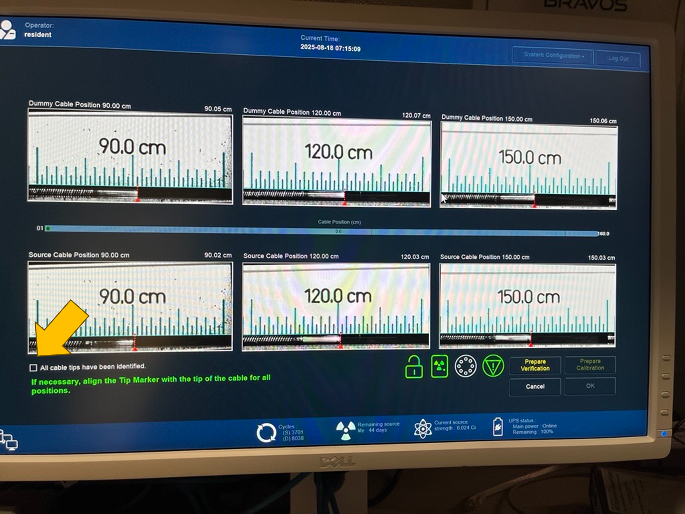
32. Verify Results
- Tolerance: ±1 mm (aim for ±0.5 mm or ±0.05 cm)
- Check the box
All cables have been identifiedif within tolerance - Click
Ok>Close>Approve
3.9 Worklist Configuration Check
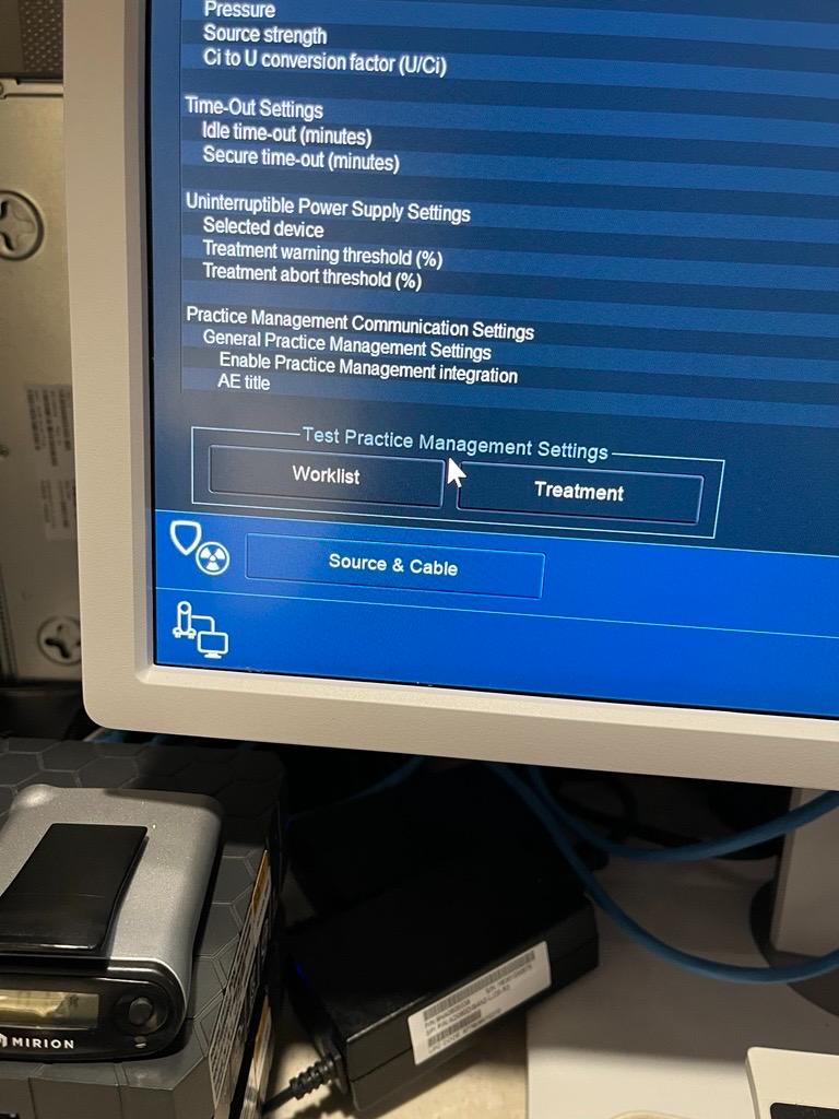
33. Verify Worklist Settings
- Select
System Configuration>Console and Afterloader>System Setting - Verify that the options for
WorklistandTreatmentappear on the bottom left
Phase 4. Creating a New Test Plan
Create a new test plan when the current plan reaches its maximum fraction count (n = 99).
34. Select Current Test Plan
- Click on the active test plan (e.g.,
4DailyQA)
35. Copy Test Plan
- Click the
Copy Test Planbutton
36. Rename Copied Plan
- Rename the copy to the next sequential number
- Example:
4DailyQAbecomes5DailyQA
37. Save New Test Plan
- Save the plan
- The new test plan is now ready for use